it seems that noise levels are lower with shunt regulated power supplies
Certainly nice to have, but technically not needed at all. A power amp is not a super sensitive phono preamp 😉
Sure, if you're already hooked, go for it.
Hannes
h_a;2554653 Sure said:Thanks Andrew and Hannes,
You are right Hannes, go for it if you are hooked and there's the rub. I'm curious to know how much difference it would make but not that curious considering the amount of work involved and the current levels of listening pleasure. Still it is interesting to learn how to for any future project.
Best wishes,
Chris
Looks good to me, the only thing I might suggest is a direct connection between the grounds of the two power supplies, then from the star ground to the front end ground. I'm not sure what the ground symbol in the diagram is meant to be, just symbolic or something physical?
Looks good to me, the only thing I might suggest is a direct connection between the grounds of the two power supplies, then from the star ground to the front end ground. I'm not sure what the ground symbol in the diagram is meant to be, just symbolic or something physical?
Dear highfieldrebel thanks for your suggestions,
I have removed the stabilized PSU (0) point from the front end (GND) and lead it to the STAR point.
The unown symbol that starts from the star in the wiring is just for the final chassis ground that ends to earth ground (could not find a correct symbol to represent ground in word format).
I am thinking also that I have to remove the wiring from (IN-) to STAR I believe that will create a humming loop.
Your comment is hily aprisiated.
Thanks
The unown symbol that starts from the star in the wiring is just for the final chassis ground that ends to earth ground (could not find a correct symbol to represent ground in word format).
I am thinking also that I have to remove the wiring from (IN-) to STAR I believe that will create a humming loop.
Thanks
For the connection between star (signal) ground and chassis, a thermistor is recommended in the BA-2 article. You could be right about the (IN-) connection, one fewer connection to STAR will help keep things tidy.
Just a little feedback - I ordered my parts from Company Store and was very happy with the product delivered. The parts were clearly organized and this was a huge time saver. I would highly recommend them.
Have you also the schematic of this model?Thanks Steve,
I was on to them this morning and you are right, they are very friendly.
I have been looking through Nelson's BA-2 advice and he says that the bias of 250 mA results in dissipation of about 6 wattts per transistor.
If one is using six then surely the power dissipation is going to be 36W not 75W which is the figure I have been using up to now?
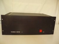
I have two old Thorens, Restek E3 monoblocks which I thought I could use for a couple of Nelson Monoblocks. Only one of the two heatsinks in each case has been drilled. Any one know what sort of heat these were designed to dissipate?
Regards,
Chris
Meine alten helden-thorens restek e3 - magnus.de Forum
http://www.thorens-info.de/trvorend_2.jpg
http://www.thorens-info.de/trvorend_1.jpg
www.tmr-audio.de/tests/audio_11_84.pdf
(test in German between Accuphase P600, Luxmann M-05, Hiraga Le class A, Krell KMA-100, Restek E3 and TMR-1000ES)
Attachments
Last edited:
Thanks for taking the trouble to reply. I can't understand a thing in German but at least I feel guilty about it. Interesting photos of the original Restek design which I haven't seen before.
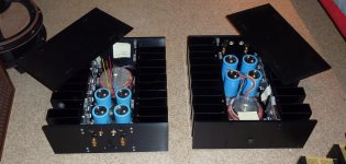
At present I have six mosfets on one of those heatsinks with a bias of about 410mA. Things don't get too hot with an ambient temp of about 22-23 deg C. So the heatsinks are coping with about 59W output from the transistors.
Best wishes,
Chris
At present I have six mosfets on one of those heatsinks with a bias of about 410mA. Things don't get too hot with an ambient temp of about 22-23 deg C. So the heatsinks are coping with about 59W output from the transistors.
Best wishes,
Chris
Help is needed for 2sj74 in terms of orientation on the Cviller"s pcb
Dear all,
Can someone advice on how to orient the (2x 2sj74) devices (Q201) on Cviller"s BA-2 frond end PCB"S.
Thanks for your help and support.
Dear all,
Can someone advice on how to orient the (2x 2sj74) devices (Q201) on Cviller"s BA-2 frond end PCB"S.
Thanks for your help and support.

2sj74 and 2sk170 and bc550 etc all have identical pin orientation.
dgs/cbe
Thanks for your help dear Andrew
BA chassis
I was wunderin if some kind soul would post the dimensions of the BA chassis in the pic here... I want to build one of these, as I think its gorgeous!,, but need some of the specs to get going,,, such as dimensions of the rectangular tubes... height, width and length of the outside of the chassis... I should be able to figure the rest 🙂
I was wunderin if some kind soul would post the dimensions of the BA chassis in the pic here... I want to build one of these, as I think its gorgeous!,, but need some of the specs to get going,,, such as dimensions of the rectangular tubes... height, width and length of the outside of the chassis... I should be able to figure the rest 🙂
Attachments
I think that design originated with the PLH project. You might find the details in that article?
Front and rear panels:
7" x 17" x 3/8"
Overall Chassis front to rear: 18 1/2"
Tube fins 4 1/2" x 1 3/4" x 6" h x 3/32" wall thickness (EDITED: I changed 1/8" to 3/32" for wall thickness)
Clear between tube fins: 1 1/2"
Top & bottom covers: 9 3/16" wide x 1/4" They overhang the central enclosure walls on the sides
External width of central enclosure: 8"
Side walls of central enclosure: 6" high x 3/8" thick
Bolt holes in front panel: 3/4" and 1.5" from top & bottom Seem to be 3/16" bolt
Bolts holding tube fins: 1" from top & bottom (2 bolts per tube)
In front Panel: LED hole 2 1/8" from top, lower switch flange 1 1/2" from bottom
I don't think the PLH has any description of them
Last edited:
Hefty, me expected something more like 5/64" to 3/32"
(boats still do inches, feet, knots, gross tons, short and long tons, sometimes even bells and fathoms)
(boats still do inches, feet, knots, gross tons, short and long tons, sometimes even bells and fathoms)
- Home
- Amplifiers
- Pass Labs
- Burning Amplifier BA-2