Apologies for a serious OT here but Hannes' post caught my eye. I need to drive for an optics experiment a piezoelectric element. According to the spec sheet it will show as a 0.4 uF capacitor and I need to put a 30 V sinewave across it at up to 50 kHz. Could someone point me towards a buffer design that could handle this load?
Thanks and apologies again for the OT
take a look at the application notes at Linear Technologies -- there are several dealing with piezo loads.
Thanks for all the replies, I'll check the Linear Technologies' site, I also have a couple of output boards from the BA-2, maybe I can repurpose one of them.
Steve
Steve
Hi All, I'm quite new here, but have been reading a lot for the couple of months to gather as much info as possible. I have tried building the BurningAmp2, but I flipped/inverted the frontend as the 2sj74 is difficult to get (don't know if i'm still allowed to call in a Burning Amp2). I have been able to complete the amp and I have had the chance to do some measurements on this one as I thought the 'top' was a bit soft allthough this might be normal for this amp.
I'll try to give as much info as possible. I've made a complete dual mono amp, 50,000uf/per rail (so that's 200,000uf in total,CRC filtered 20mF-0.11R-30mF per rail), 2x 250VA, 18Vac toroids which give me about + /- 25Vdc after rectification. Bias is about 1 Amps (total per channel)
The front end is on a seperate PCB, and the bias+output stage on another PCB.
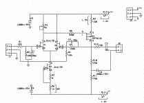
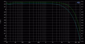
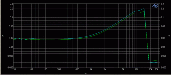
Now, I've noticed that the amp has a limited bandwith, and that there's some weird distortion in higher frequencies. I have used a IRF9610 (brand Siliconix) as VAS. Could this be the 'IRP channel problem' what Nelson is talking about?
Also good to know is that i get almost exactly the same measurements when I disconnect the output stage and measure directly on the output of the VAS.
Static measurements are ok : I have the 10mA from the css, can alter the DC output to zero, etc...
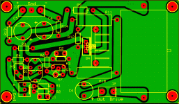
I've attached the schematic I'm using, the PCB layout of the frontend, bandwith measurement and THD. Measurements has been done with balanced input.
Does anyone know what I have done wrong or if this is normal? Could it be that I've just done a bad job at designing the Frontend PCB 🙁... Would it help if I'd remove the copper area? I must say that the real PCB has a lot more clearance between the gnd area and traces as it appears in the picture. Both channels behave in exactly the same way as you can see in the graphs. Measurements has been done with and without load, but this doesn't improve anything. Maybe I have bought counterfeit 2SK170's, or counterfit IRF9610?
Attachments
Really, Silioconix IRF610?...the amp has a limited bandwith, and that there's some weird distortion in higher frequencies. I have used a IRF9610 (brand Siliconix) as VAS. Could this be the 'IRP channel problem' what Nelson is talking about?...
My understanding was that Vishay baought the IRF610 line of devices lock stock and barrel. Processing equip and all from IR back about 2005. Siliconix was already an existing company that had been boaught by Vishay decades earlier? You actually can read Siliconix logo's on these parts?
Thery are likely Vishay and not siliconx? And they woulld have the 1-2k and higher distortion phenomina of the IR parts?
You can always test the parts easy enough. A piece which includes testing
for this issue is in the article on Mosfet testing on the Pass Diy
site. And it's not the end of the world, either.
If the problem exists in this part, you have an opportunity to listen to it
and some other in comparison. At this time I think the best alternatives
are the Toshiba 2SJ313 (P ch) or 2SK2103 (N ch).
😎
Really, Silioconix IRF610?
My understanding was that Vishay baought the IRF610 line of devices lock stock and barrel. Processing equip and all from IR back about 2005. Siliconix was already an existing company that had been boaught by Vishay decades earlier? You actually can read Siliconix logo's on these parts?
Thery are likely Vishay and not siliconx? And they woulld have the 1-2k and higher distortion phenomina of the IR parts?
I think this is the Siliconix logo, I'm not 100% sure either..I have attached a picture. I have the same logo on my output MOSFETS (IRFP240/IRFP9240)
You can always test the parts easy enough. A piece which includes testing
for this issue is in the article on Mosfet testing on the Pass Diy
site. And it's not the end of the world, either.
If the problem exists in this part, you have an opportunity to listen to it
and some other in comparison. At this time I think the best alternatives
are the Toshiba 2SJ313 (P ch) or 2SK2103 (N ch).
😎
I have have tested these MOSFETS and JFets using your method as described in the article, and they behaved normally and as expected... I agree that this is not the end of the world, but I'm keen on knowing what went 'wrong', just to learn from the experience . I'll try and build a small test-setup to check the behaviour of the VAS, and see if this one is responsible for the strange THD curve.
I will try getting a hold of the alternative that you have suggested and experiment a bit more with the VAS. Thanks Nelson.
Attachments
Vishay sent out a bulletin that the logo on the MOSFETs had been changed once they ran through their stock of International Rectifier parts. Digikey and others alerted purchasers to this fact.
As far as I can determine, the devices were made in Italy, Mexico and China. New parts are not labeled as to their country of origin.
As far as I can determine, the devices were made in Italy, Mexico and China. New parts are not labeled as to their country of origin.
Also, if the feedback is taken from that drain of the VAS fet and not the output, doesn't this limit the performance of the entire amp to that of the ouput stage since it is not included in the feedback loop?
From Cheff's UP Amp thread, post #46
http://www.diyaudio.com/forums/pass-labs/108683-ugs-power-its-u-p-5.html
I spent some time listening and comparing the global/local feedback configuration, and guess what... 😉
How to put words on that...I must mention here that all the following is purely subjective, and that it involves pretty tiny and diffuse impressions 🙂
Compared to the original global feedback scheme, I feel the local feedback comes closer to the AX. I know it's not the same topology, but the the sound becomes a bit more lusher and warmer in the bass/mid part of the spectrum, and that the highs are rolled off a bit. What I call the "AX fuzzyness" comes back again, but with much less noticeable than in the AX's case, and it narrows the scene a bit (it's a very very thin difference). The sound seemed to have lost some air.
Since the output mosfets are no longer in the FB loop, I think they bring their own character to the sound, but may be I'm wrong...
But don't get me wrong, the sound remains quite superb, and some of you may prefer the local FB configuration for its warmer aspect. It all depends on the rest of your system, so feel free to compare and choose 😉
THanks Itsmee. I read this thread some time ago and for whatever reason did not connect the dots. A lot of things don't connect well these days.😀
Can anyone tell me whether the caps in a pi filter C1-R-C2-R-C3 should all be the same value? I have one of these with C1, C2 and C3 all at 4700uF, however, I realise that there was a 1000uF cap left in the circuit before the new arrangement was installed. So I now have C4-C1-R-C2-R-C3 where C4 is 1000uF.
Best wishes,
Chris
Incidentally, the BA-2 is the gift that keeps on giving. Still enjoying superb sounds!
Best wishes,
Chris
Incidentally, the BA-2 is the gift that keeps on giving. Still enjoying superb sounds!
...I realise that there was a 1000uF cap left in the circuit...
Leave it in, the more the merrier.
Thanks Itsmee.
I have been tinkering with the power supply this afternoon. I have some inductors (no value but wire wound and I assume ferrite in the centre but maybe not) and I connected one across the second set of resistors. Different sound entirely--less veiled, brighter altogether but not hard. I prefer the sound of the inductor to the resistors.
Best wishes,
Chris
Last edited:
Hi,
what is the input impedance of the output stage? How could it be increased to make possible of using smaller coupling cap than 10uF?
Thanks.
what is the input impedance of the output stage? How could it be increased to make possible of using smaller coupling cap than 10uF?
Thanks.
Has anyone fitted a voltage regulator to the front end of the BA-2 yet?
I was looking at some possible solutions and I've got round to thinking a separate transformer rated at 50VA with secondaries at 25V would do (35V after rectification approx). I reckon 25 volts for the BA-2 front end + 4volts headroom for the reg + 1 volt for the rectification. Can't find a transformer at 22V off the shelf.
Chris
what is the input impedance of the output stage? How could it be increased to make possible of using smaller coupling cap than 10uF?
It's about 7.5K. I would not reduce the coupling cap unless you want to
start suffering loss of low end response.
😎
It's about 7.5K. I would not reduce the coupling cap unless you want to
start suffering loss of low end response.
😎
Thank you. If I increase the 15k resistors, going from rails to gates, to 33k I will double the input impedance to 15k, right?
I think there is a necessary amount of current for the TL431 to operate correctly and raising the 15k resistors will lower that current. Possibly to low 😀
I think there is a necessary amount of current for the TL431 to operate correctly and raising the 15k resistors will lower that current. Possibly to low 😀
In datasheet for TL431 is that recommended range of operating cathode current is between 1mA and 100mA.
- Home
- Amplifiers
- Pass Labs
- Burning Amplifier BA-2
