I'm thinking thermal switch, one on each heatsink, 1987-1988 (The P gear too).
Compared to other books titles, a bit of a relief to have on a highschool English lit. list in the late '70s, compliments of my 1st rate teach back then (and a F hippie)
Compared to other books titles, a bit of a relief to have on a highschool English lit. list in the late '70s, compliments of my 1st rate teach back then (and a F hippie)
Attachments
Last edited:
I have just finished my BA2 monoblocks (3 pairs of MOSFETs, 0.5 A each at the moment). Big thanks to Nelson and all involved in the creation and delivery of the amp and PCBs, it's fantastic for a DIYer like myself to have access not only to high performance equipment but also cogent explanations as to how they work.
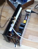
The case is interim and super-simple until I decide what to do with the amp longer term. All the PCBs are mounted onto the heatsink, the power supply is on an Al plate of equal dimensions as the heatsink. Four pieces of M4 studding are used to join the two sides, threaded through the heatsink, when the nuts are tightened the construction is surprisingly rigid. Two cables run between the sides carrying power and grounds, the connector visible is a disk drive connector and pulls apart easily enough. The case opens like a book so you can get good access to the parts while the amp is working. One question I had before assembly was how close the transformer could get before causing problems, in actuality the width limitation is given by the height of the capacitors, I never notice any hum.
I did have an issue with biasing one of the channels: I adjusted P101 to increase the current but P102 reached its limit and was unable to make OUT zero volts beyond 360 mA bias. I soldered a 330 ohm resistor in series with R125 and I was able to zero OUT at 500 mA. Looking at the circuit, it seems to require the Vgs of the 9240's to be less than the Vgs of the 240's. Is this something well known about MOSFETs?
Attachments
Nice clean build you have here 😉 Enjoy!
No, it's usually the other way 'round.
Hannes
Vgs of the 9240's to be less than the Vgs of the 240's
No, it's usually the other way 'round.
Hannes
DC offset--problem or not?
I have also completed the other monoblock and have been biasing them at 420mV. The heatsinks seem happy at this level and I'm not having any problem setting the d.c. offset to zero. However, I've noticed that the reading across the speaker terminals does vary slightly from one testing session to another reading between 0V and 5mV. Is this acceptable (could it be the multimeter isn't that accurate?) and at what voltage does this become a problem.
Best wishes,
Chris
Thanks Itsmee.
Highfieldrebel a question. It looks as though you are using a mains filter unit as your IEC socket. I have played around with these before and have noted a reduction in dynamics when using them. Have you tried just using the dual 3n3 caps only?
Best wishes,
Chris
Highfieldrebel a question. It looks as though you are using a mains filter unit as your IEC socket. I have played around with these before and have noted a reduction in dynamics when using them. Have you tried just using the dual 3n3 caps only?
Best wishes,
Chris
I thought I should tie off post #742 in case I've caused any concerns, I traced the issue I had with zeroing the DC back to a power supply fault that gave me a 1V difference in the magnitude of the +ve and -ve rail voltages.
There's about 1.3 mA passing through P102, giving a 1.3V range, I was just outside this.
I measured the voltage between the gate and source for the n-type and p-type MOSFETs, at a variety of currents
current [mA] N [V] P [V]
100 4.19 3.97
200 4.34 4.08
300 4.47 4.08
400 4.56 4.21
500 4.62 4.25
600 4.67 4.29
So, the 0.35 V difference, combined with the 1V rail difference put me just outside the 1.3 V compensation range of P102. The PSU is fixed now, so I've removed the 330 Ohm resistor and I'm back to the proper schematic.
Backbones - I've only tried the mains filter unit that's in the photo.
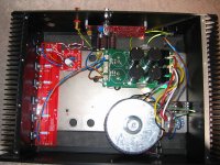
I have just plugged the two monoblocks into the stereo system.
Sound in a nutshell is superb. Expressive and detailed bass with weight. Low background noise allowing low level detail to surround the instruments with a real sense of presence. Big warm detailed piano sounds and great timing.
For those of you not sure about this project let me tell you that this is one of the finest amps I have ever listened to at any price. It doesn't sound good it sounds beautiful.
I would just like to thank Nelson for his inspiration and humanity which has allowed this project to get off the ground and all of you on this site without whom I would have been a sadder and less fullfilled individual (I can do Oscar speeches after all).
I have included a top down shot of one of the monoblocks (which is like the other one but slightly different).
Best wishes,
Chris
Attachments
Looks good Chris, what bias are you running through your MOSFETs? Any chance you'll utilise the other heatsink for more MOSFET pairs?
Steve
Steve
Hi Steve,
Bias of 410mV across the 1ohm resistors. The chassis is an old Thorens Restek monoblock and at this level of bias the heat levels are comfortable with ambient temp of about 20.5deg C.
At present I can't see a reason to add more mosfets as the sound is superb nevertheless it is an option.
Best wishes,
Chris
At present I can't see a reason to add more mosfets as the sound is superb nevertheless it is an option.
Best wishes,
Chris
I can't see a reason either, beyond curiosity. I have a feeling curiosity will win. Has anyone opined as to the outcome of adding more, beyond the notes NP made in his article?
S
Complementary Bipolar Output
"There were even a couple of amplifiers with complementary bipolar output stages."
Any news on this variant Mr. Pass?
Thanks!
"There were even a couple of amplifiers with complementary bipolar output stages."
Any news on this variant Mr. Pass?
Thanks!
"There were even a couple of amplifiers with complementary bipolar output stages."
Any news on this variant Mr. Pass?
No. They were simply darlington followers which can be
used in place of the Mosfet stage. Its equivalent looks
like this.
😎
Attachments
Complementary Bipolar Output
Thanks!
No. They were simply darlington followers which can be
used in place of the Mosfet stage. Its equivalent looks
like this.
😎
Thanks!
The zeners marked D101 and D102 on the output board, how important is it that they are exactly 1N4739?
I have 1N4007, 1N4004 and 1N4148. Can I use any of those as substitute or is it imperative to use 1N4739?
Kind regards
/Forsman
I have 1N4007, 1N4004 and 1N4148. Can I use any of those as substitute or is it imperative to use 1N4739?
Kind regards
/Forsman
Last edited:
Zeners are not regular diodes at all. Use wikipedia for this one. It will become obvious very quickly why they are different and its a good thing to know.
Zener diode - Wikipedia, the free encyclopedia
If you dont read the whole thing at least read this part
http://en.wikipedia.org/wiki/Zener_diode#Uses
Uriah
Zener diode - Wikipedia, the free encyclopedia
If you dont read the whole thing at least read this part
http://en.wikipedia.org/wiki/Zener_diode#Uses
Uriah
Hi
I have trublle finding the specific Zeners where I live but I have bought a coupple that I think should be equivalent. Do you think I can repalce 1N4739 with BZX 55/C9V1?
/mvhff
I have trublle finding the specific Zeners where I live but I have bought a coupple that I think should be equivalent. Do you think I can repalce 1N4739 with BZX 55/C9V1?
/mvhff
- Home
- Amplifiers
- Pass Labs
- Burning Amplifier BA-2