
Programming semantics:
- sqrt(2) is a function call that returns the square root of 2
- 2^0.5 or 2^(1/2) is an arithmetic expression of square root of 2
- sqrt*2 is an error 🙂
- sqrt(2) is a function call that returns the square root of 2
- 2^0.5 or 2^(1/2) is an arithmetic expression of square root of 2
- sqrt*2 is an error 🙂
Hello!
I've got a question concerning the adjustment of the BA-3b.
Is there the possibility (it would be more easy) first to power up one (single ended) channel, then the next, then unsolder R5 from ground and tie it together?
Or should I power up the balanced channel by adjusting both P1, P2. P101, P102 one after the other in small steps?
Thanks for the help!
Matthias
Hm,
I think "Ich stehe auf dem Schlauch!", means I feel I don't get it.
So have the BA-3b soldered (with R5 tied together and not to ground):
a) set all trimmers (but P3) to 0 Ohm
b) slowly adjust P1 and P2 on one half (as described in BA-3 manual)
c) then the same for the other half of this symmetrical channel.
Is this right?
Gute Frage, Murdoc! a good question Murdoc!🙂
I adjusted both halves of the BBA-3 one after the other.....😛
but your reflection if you should ground R5 first for one half, is understandable...
as far as I understand Nelsons explanation the R5 is more important for the AC current flowing....😀
so I think the DC adjustment is not so much influenced by the still not working half when adjusting the first one...
But of course you can prove by going back to the first half after the adjustment of the first....
But doing it separately did no harm to the front stage.....!😀
Thanks a lot, Gerd!
My kitchen table is stuffed with the case, BA-3 boards, salas boards, toroids, net filter(s), cables, tools, more tools, and 3 old but nice multimeters, one digital, the others analog (good old Metrawatt)! So it's time to get it to work, put all (only the necessary 😀) modules into the case and tidy up.
My kitchen table is stuffed with the case, BA-3 boards, salas boards, toroids, net filter(s), cables, tools, more tools, and 3 old but nice multimeters, one digital, the others analog (good old Metrawatt)! So it's time to get it to work, put all (only the necessary 😀) modules into the case and tidy up.
Last edited:
Hello,
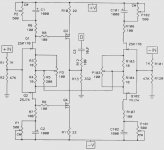
I need balanced inputs for the front end of BA3 connected with the official BA # 1 single-ended output stage.
What do you think of this schematic?
Thank you for your answers
Regards
Darry
ZM, I am confuzed. How does the negative side affect the signal? This presents a learning opportunity, as I have not seen this before.
benefit ......... besides already mentioned conversion from balanced input to unbalanced output stage , is everything you get with symmetry in stage , along with special shaping of THD content
if that's not enough significant , I don't know what is
if that's not enough significant , I don't know what is
i get the practical part of a balanced signal and all that you gain in terms of transmission along interconnects and harmonic cancelation within an amp, but what i do not understand is how it is happening in this amp. What ia happening with the negative signal and how does it affect the final signal leaving the FE from the positive side. I think it is time to go draw some squiggly lines on a schematic and stare😀
....... I think it is time to go draw some squiggly lines on a schematic and stare😀
couldn't agree more ........
just be aware of fact that whatever happens to your left leg is always influencing your right leg ....... and the other way ;
take that analogy to this circ
you can jumping on one leg , but hardly without swinging with other one
Last edited:
If I wanted to get the dissapation of the output stage (ba-2) down to 300w when used in balanced configuration, would the only options be either half the rail voltage or have the bias? I guess neither one of these is very desirable. Thanks for any input..this whole balanced thing is very new to me, but it would be nice to pair up with the bufflo dac.
Dave
Dave
Balanced ClassA bias current is tied explicitly to speaker impedance.
If you adopt 16ohm speakers then the dissipation can be halved.
I'll remind you of the "rule" for balanced and bridged amplifiers: They deliver twice the power into twice the impedance.
If you adopt 16ohm speakers then the dissipation can be halved.
I'll remind you of the "rule" for balanced and bridged amplifiers: They deliver twice the power into twice the impedance.
Last edited:
I will be making up balanced BA3 FE connected to BA1 output, BA2 output, and circlotron output.
The plan is to put the front end in it's own case with shunt regulator (most likely a Salas shunt) and the output stage in another case with CRC power supply.
For the BBA3-BA1 output, I am thinking +/- 22V supplies and 5A per output phase for a total of 10A drawn from the power supply. So it is definitely going to be monoblocks.
Has anyone tried this yet?
Last edited:

- Home
- Amplifiers
- Pass Labs
- Burning Amp BA-3b (Balanced)