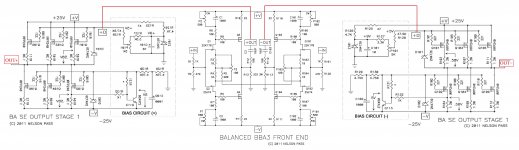
Assuming you mean 6 pairs, like in schematic in post #505.
Yeah that is close enough if we are talking approximations.
i mean 6 devices (3pairs) on each half balanced.
so 3pairs for positive and 3pairs for negative side.
2 x 600VA Transformers with 24VAC secondaries is borderline acceptable.
800VA would be better.
But if you already have them you may as well give it a try. You may or may not get some mechanical transformer buzzing. If the transformers are noisy then you may need to reduce the bias or buy bigger transformers.
If you do decide buying new transformers is necessary, then 18V to 20V AC secondaries is more than adequate to give you 100W in a balanced circuit.
i will consider that.
We will need to modify the biasing circuit for the negative rail or consider using different source resistor for CCS (around 0.75Ohms)
Or leave biasing circuit unmodified and run 8 or 9 pairs instead of 6 pairs
i don't understand what you mean modifying negative rails bias circuit?
why only negative side?
thanks.
i mean 6 devices (3pairs) on each half balanced.
so 3pairs for positive and 3pairs for negative side.
i don't understand what you mean modifying negative rails bias circuit?
why only negative side?
thanks.
1) So half the number of devices of the schematic you posted?
2) Biasing of the CCS is fixed at around 0.6V across the source resistor of the CCS mosfet.
Biasing of the mosfet from the positive rail is already adjustable through P101.
No problem though we can make it adjustable by addition of suitable value for R131 in your schematic
Last edited:
1) So half the number of devices of the schematic you posted?
2) Biasing of the CCS is fixed at around 0.6V across the source resistor of the CCS mosfet.
Biasing of the mosfet from the positive rail is already adjustable through P101.
No problem though we can make it adjustable by addition of suitable value for R131 in your schematic
yes half the number,
please see new attachment.
Attachments
Last edited:
Now we are getting somewhere.
However 1.67A per device (for 5A on each half of balanced circuit) won't be feasible with over +/- 30V rails
However 1.67A per device (for 5A on each half of balanced circuit) won't be feasible with over +/- 30V rails
1A per device is the most you would want to run them that.
That would make it 5 pairs on each half of balanced circuit.
That would make it 5 pairs on each half of balanced circuit.
Just as a general comment, with your existing transformer secondary voltages it would make sense purely from technical/textbook point of view to use push pull output stage.
However that doesn't mean you should do that.
If you're heart is set on single ended then you should proceed as planned.
However that doesn't mean you should do that.
If you're heart is set on single ended then you should proceed as planned.
Just as a general comment, with your existing transformer secondary voltages it would make sense purely from technical/textbook point of view to use push pull output stage.
However that doesn't mean you should do that.
If you're heart is set on single ended then you should proceed as planned.
What sort of power supply do you have planned?
so that's mean 24Vac (32Vdc) is too high for single ended followers?
i plan to use separated psu between the front end and the output stages.
front end will use regulated psu, output stages will use CLC's.
at least that's what i think for this moment.
so that's mean 24Vac (32Vdc) is too high for single ended followers?
No not too high.
But you are generating extra heat heat, since you only need around 23V dc rails for 100W.
600VA transformers is not going to be adequate.
5A on each half (10A total per channel) with 32V dc rails will be a total of 640W of heat per channel. You will need 2 x monster cases. You will need something like 2 x 1.5kVA transformers for dual mono.
Must have had a brain fart before thinking 600VA might be ok.
Last edited:
No not too high.
But you are generating extra heat heat, since you only need around 23V dc rails for 100W.
600VA transformers is not going to be adequate.
5A on each half (10A total per channel) with 32V dc rails will be a total of 640W of heat per channel. You will need 2 x monster cases. You will need something like 2 x 1.5kVA transformers for dual mono.
Must have had a brain fart before thinking 600VA might be ok.
I would suggest limiting the heat to around 280W per channel and work backwards
i see... it is about the heat dissipation.
so i think it would be wise to replace the transformers with smaller secondary voltages, rather than insist to use what i have now which can cause money dissipation at the end. 😀
thanks for the advice.

so i think it would be wise to replace the transformers with smaller secondary voltages, rather than insist to use what i have now which can cause money dissipation at the end. 😀
thanks for the advice.
If you wanted to use what you have the most logical course of action would be the following.
32V rails
Balanced Push Pull Output stage
Each half circuit biased at 2.1A
Result:
70W of Class A
Then klunk into Class AB to approximately 220W
Staying with the single ended approach:
Use your existing transformers with regulators to power the BA3 front end of the circuit.
Then for the output stage you will need 2 x 1kVA transformers with 18V AC secondaries
2 Cases capable of dissipating 460W each
Use your existing transformers with regulators to power the BA3 front end of the circuit.
Then for the output stage you will need 2 x 1kVA transformers with 18V AC secondaries
2 Cases capable of dissipating 460W each
If you wanted to use what you have the most logical course of action would be the following.
32V rails
Balanced Push Pull Output stage
Each half circuit biased at 2.1A
Result:
70W of Class A
Then klunk into Class AB to approximately 220W
no, i stick with the single ended.😀
Staying with the single ended approach:
Use your existing transformers with regulators to power the BA3 front end of the circuit.
Then for the output stage you will need 2 x 1kVA transformers with 18V AC secondaries
2 Cases capable of dissipating 460W each
600va for the front end is real redundant.
1A transformer is more than enough for FE, so i will use the little one i have.
can you explain how you calculate which ended with the need of 2 x 1kVA transformers?
thanks.
A 1kVA 20-0-20Vac transformer has a maximum continuous AC current of 25Aac
If you pass that into a capacitor input filter, then the maximum continuous DC output current is approximately 13Adc.
The transformer will run hot all the time.
If you reduce your loading to ~50% the transformer will have a long cooler life.
Try ~ 6Adc to 7Adc as a continuous rating for the bias current.
7A total bias in a balanced single ended amplifier driving an 8ohms load will give a maximum output power of 49W
Quiescent dissipation will be ~390W.
Balanced and single ended is killing your project.
Last edited:
no, i stick with the single ended.😀
600va for the front end is real redundant.
1A transformer is more than enough for FE, so i will use the little one i have.
can you explain how you calculate which ended with the need of 2 x 1kVA transformers?
thanks.
1) If you have smaller transformers then definitely use those on the front end.
2) Basically double the heat dissipated value then round up to the next VA rated transformer. In your case 460W of heat per channel. 460 x 2 = 920, that rounds up to 1000VA (1kVA)
A 1kVA 20-0-20Vac transformer has a maximum continuous AC current of 25Aac
If you pass that into a capacitor input filter, then the maximum continuous DC output current is approximately 13Adc.
.
He is planning on 10A DC continuous on a 1kVA transformer with lets say 18V AC secondaries (20V is also an option)
no, i stick with the single ended.😀
.
Before you purchase the transformers start looking at cases capable of 460W each.
They are going to be big
One of these cases will safely do 400W Dissipante 5U 500mm frontale 10mm NERO coperchi e retro in alluminio 3mm
If you are extremely lucky it might do 460W but you will need to email them
If you are extremely lucky it might do 460W but you will need to email them
He should be able to work out that 10Adc from a 1kVA 18-0-18Vac transformer uses ~71% of it's maximum rating.He is planning on 10A DC continuous on a 1kVA transformer with lets say 18V AC secondaries (20V is also an option)
He needs to decide if his transformer will have a reliable life.
- Home
- Amplifiers
- Pass Labs
- Burning Amp BA-3b (Balanced)