probably:
like past 240° of 270° used too often.
or
starting at 6o'clock and finishing at 3o'clock, I need to use 2o'clock often. o'clock is the english short form of "of the clock".
Do you ever get to 270°?
There is nothing wrong with using 200° or 240° or 269° of a 270° vol pot.
It's when you need 275°, that you have run out of gain.
Do you ever run out of gain?
Is that only with a few Sources?
Consider adding a switchable gain block to be used ONLY with low level sources.
Last edited:
Thanks for the explanation.
I know that there is nothing wrong, on the contrary. But yes, with some sources I run out of gain.
I know that there is nothing wrong, on the contrary. But yes, with some sources I run out of gain.
............................
Consider adding a switchable gain block to be used ONLY with low level sources.
................ with some sources I run out of gain.
I havent built the BBA-3 monos yet, but I will build a BBA-3 pre to feed it, I have a Pumpkin Kit around here, but I will probably start with BBA-3 pre.
If you are using unbalanced B-1 w/o enough gain, just build a BA-3 front end. I use one with my normal 31 volt rail BA-3 amp...plenty of gain.
Russellc
If you are using unbalanced B-1 w/o enough gain, just build a BA-3 front end. I use one with my normal 31 volt rail BA-3 amp...plenty of gain.
Russellc
In searching for a BOM, bill of materials, for the BA3B ( BA-3B , BBA-3, Balanced BA-3 , BA3 - adding other search synonyms for same item just in case this page has a hit with a link to the current answer) the only search result that comes up in a narrowed down search is the earliest referral to a BOM on the old DIY Audio store. Nice upgrades to the selection in the store by the way.
I'm trying to see the number of each board needed and their arrangement, to get an estimate on the cost to build one to drive a pair of F4 balanced. The BA-3b version I need will be for unbalanced input with balanced output. There seem to be a lot of ways to build variations, trying to keep it as straightforward as possible for this application.
I'm not trying to be lazy, but haven't been able to find it over the last couple of weeks. Maybe there is someone subscribed to the tread that knows what I'm looking for. Thanks in advance.
Yes, considering other options than the BA-3b but don't want to mention them as it may hinder search results for others with the same question in the future.
Last edited:
SE in BAL out needs one BA-3 front-end PCB per channel. That front-end will need to be configured as in the BA-3B configuration. Just attach the -in to ground for SE input operation.
sorry if I missed that, but once the FE/gain board is configured for balanced, how does one use now 6 trimpots to make the needed settings?
Does one look at negative and GND and do one half of the board trimming 3 pots, and then look at + and GND and use the other three pots for the other side. Or should one start looking at + and - and work on both sides at once?
this question becomes even more applicable to making distortion settings via P3. 😕
I am about to start tuning my BA-3b monoblocks and I could use a qualified input; especially when it comes to looking at distortion (since this will be the first for me). I was thinking of setting it for minimum distortion since my balanced volume control will come with AlephP in front of BA-3bs which will add its own distortion to it.
The P1s and P2s will still do the exact same thing - they set bias and adjust DC offset, you'll have to make them all match, but as it's basically 2 discrete channels per channel, there's nothing mysterious about the process, just a bit time intensive.
As for P3, well then you are on your own, set to measured neutral on all channels and if you want to adjust, get a distortion analyzer and then ask Papa for advice.
As for P3, well then you are on your own, set to measured neutral on all channels and if you want to adjust, get a distortion analyzer and then ask Papa for advice.
sorry if I missed that, but once the FE/gain board is configured for balanced, how does one use now 6 trimpots to make the needed settings?
Does one look at negative and GND and do one half of the board trimming 3 pots, and then look at + and GND and use the other three pots for the other side. Or should one start looking at + and - and work on both sides at once?
this question becomes even more applicable to making distortion settings via P3. 😕
not sure what to make of the one answer. my question as to what to measure and how many pots to fiddle with at the same time was pretty specific.
I can probably get the bias and Dc offset right by figuring it out on my own, but I am pretty fuzzy on reducing distortion with one pot on each half, and if each side can be worked on independently or interaction demands both be worked at the same time. Papa? zenMan?
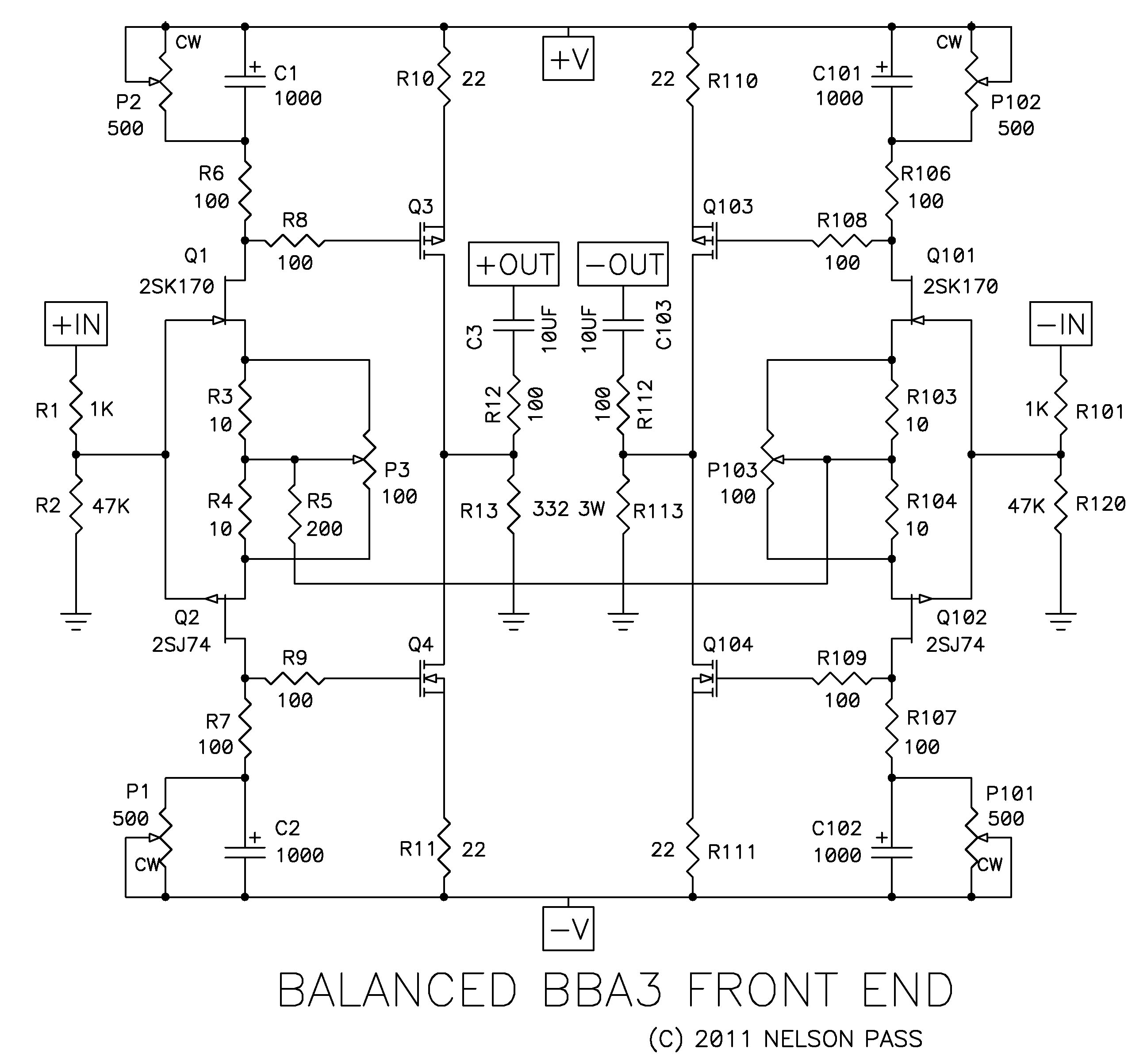
first let me know which pcb you're using , so I can see what arrangement of R5 (ref. to schematic you posted) you're having
Bias/DC offset will be done individually for each phase of each channel. Set bias and offset of L channel +, then L channel -, and repeat for the other side.
As for P3, I would begin with the pots in their measured neutral position.
Here is what I would do if you wanted to change them - (and this assumes you have the proper tools to do so, you can't do this by ear...) set P3 on each channel so that either the 1) distortion residual measures the same and has the same shape, or 2) if using FFT, so the 2nd and 3rd harmonic peaks are the same per phase. Set each phase to the desired amount and then in turn set the other channel to match.
If you want to set for absolute minimum distortion (which I suggest you don't, it's not particularly good sounding) you will need to make all 4 phases match the distortion figure of the channel/phase with the highest minimum distortion.
not sure what to make of the one answer. my question as to what to measure and how many pots to fiddle with at the same time was pretty specific.
I can probably get the bias and Dc offset right by figuring it out on my own, but I am pretty fuzzy on reducing distortion with one pot on each half, and if each side can be worked on independently or interaction demands both be worked at the same time. Papa? zenMan?
I am using the BA-3 gain stage (red board) from DIY store. for R5 I use 100ohm on each side and then connected to each other.
p.s. as a sidenote only: for output stage I use F4 boards.
now I got the DC offset/bias portion from 6L6: I was going to do it that way, short both IN+ and IN- to gnd, then look at OUT+ to gnd and trim one side, then look at OUT- to gnd and trim the other side, right? bias of course considered simultaneously with DC offset, one side at a time.
for P3: I have an FFT analyzer (BNC in) and I have a SE signal generator (BNC out). so I bring a signal say at 1 kHz to one half input (plus/gnd) and trim one side while sampling the same sign output pls/gnd (to calculate the spectrum and look at the orders). then bring the same signal with inverted polarity to input minus/gnd and trim the other P3 while sampling and looking at FFT of output minus/gnd. Does that sound right or ....?
Last edited:
in some cases it's possible to use both signal generator and analyzer in floating arrangement , with BNC hot connected to positive and BNC gnd connectedd to negative input/output
you can try that in steps - first connect gene , and observe is there any trace of hum
then proceed with analyzer on output , observing what reading are - are they logical or messed with forced connection
if that is not possible , you must proceed with true balanced input and output connection
regarding pcb question - best way is , for initial settings (start with ohmmeter confirmed mid setting of P3/P103 ) , to start with temporary grounded joint point of R5 halves ; that way you can independently set working parameters (Iq , output offset) of left and right halves
after that ...... pray , for God being on your side
Ok, temporarily grounding the mid point between the two R5s is the key piece of info I was missing to do each half independently. Thanks ZenMan. 
on the distortion part, I will tread carefully. I will post back what I ended up doing. it may take a while though (like everything with my amp/spk work).
based on what others were saying apparently the distortion with 2nd order and 3rd order being about equal sounds the best. that is for the nominal SE version. I have not seen anything posted about the balanced version where some 2nd order cancelling supposedly takes place.
you can set it in same manner , it's easy to unbalance it in proper way
I mean - not fast easy but possible easy
I mean - not fast easy but possible easy
BA3B + BA2 mono block power output
Looking at Nelson's second post on this thread, it appears that at 0.1% THD, the BA3B w/complementary BA2 output stage at +/- 24V DC, has a power output of 100 watts, and at +/-32V DC, it is about 160 watts into I'm assuming, 8 ohms.
Can anybody hazard a guess/calculation on what it would be at +/- 20V DC (the lowest recommended PS rail per 6L6's excellent BA-3 amplifier illustrated build guide)? 😕
Thank you,
Anand.
Last edited:
Power is VRMS squared divided by load in ohms.
The balanced BA-3 can swing voltage to roughly 10% of the rails, where the source resistors start to steal a bit of output.
20V rails, on a balanced amp is 80V pk-pk, -10%, so it can swing ~72V
72V pk-pk is equal to 25.4V RMS (72 x .3535)
25.4^2 = 647.8 / 8(ohms) = 80W (which is actually close enough to 60W as to make little meaningful difference...)
And there are enough output devices on this amp to be able to give full output current into 8 and 4 ohms as well.
That said, if you have the transformer on hand, by all means use it and don't think twice, but if you are buying one, buy a 18+18v or 20+20v
- Home
- Amplifiers
- Pass Labs
- Burning Amp BA-3b (Balanced)