so you have a BalancedBA-3 Frontend and two outputstages for one channel?
And again how many pairs for one outputstage?
And again how many pairs for one outputstage?
koja , for proper setting of P3 (yes ,it'll invoke 2nd above 3rd) , you need balanced feed from gene
how you are going to make that , matter of your wit
Papa certainly more than chewed operation of balanced BA3 circuit ( for other purposes) but we can't expect him to spit out just everything ...... that would be more than few full time jobs
how you are going to make that , matter of your wit
Papa certainly more than chewed operation of balanced BA3 circuit ( for other purposes) but we can't expect him to spit out just everything ...... that would be more than few full time jobs
Thanks ZM. Good to know that it can do 2nd order. I will get to playing with the distortion when the time permits. given my other open projects probably towards the year end.
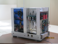
the amps work fine. the only issue is that the FE card is mounted on a vertical plate and as the heat moves up the upper Toshiba pair runs really hot (I can put my finger on the heatsink for about 2 sec only). So I am thinking of cutting some copper tabs and adding a bit of heatsinking surface.
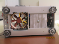
If you do not know how I make my amps I attach here a few pics. I use a fan for the main heatsink i.e. for cooling the output stages. the section right behind the front panel though has no forced air flow. I have a control board there and the balanced FE board. I do not feel like taking some fets off the board to mount them on the vertical plate (1/4 inch Alu) which should definitely do the trick but it would look ugly with wires etc.
each mono block PS has over 450,000uF in capacitance. so this vertical layout works for the most compact package.
the amps work fine. the only issue is that the FE card is mounted on a vertical plate and as the heat moves up the upper Toshiba pair runs really hot (I can put my finger on the heatsink for about 2 sec only). So I am thinking of cutting some copper tabs and adding a bit of heatsinking surface.
If you do not know how I make my amps I attach here a few pics. I use a fan for the main heatsink i.e. for cooling the output stages. the section right behind the front panel though has no forced air flow. I have a control board there and the balanced FE board. I do not feel like taking some fets off the board to mount them on the vertical plate (1/4 inch Alu) which should definitely do the trick but it would look ugly with wires etc.
each mono block PS has over 450,000uF in capacitance. so this vertical layout works for the most compact package.
Attachments
Last edited:

I believe I have boards for a BBA-3 Balanced Front End, for putting in front of a pair of F4's.
I don't have any form of a BOM, other than a diagram. On that diagram it doesn't state what Q3/Q4 are... but am wildly guessing IRFP240/IRFP9240's.
Alweit has been my source so far, and I try to support the DIYAudiostore as well and am open to other trusted sources.
One of the few things I have learned in this hobby working with existing BOM's usually results in rework and re-ordering of parts... I could have bought a "good enough" amplifier off the shelf with what I have paid to shipping companies over the last few years.
Is there a recommended current BOM if I were to go with either Alweit's "Toshiba Original 2SJ74GR / 2SK170GR Matched Pair (0.05 mA)"? I don't know how to match, have very little understanding this project. Jumping ahead just a little.
I'm still trying to get the F4's to a place where they can be biased.
Hi Jeffs,
Q3 and Q4 can be as they are in the BA-3 front end: 2SJ313/2SK2103 or FQP3P20/FQP3N30. I would imagine some resistors/pots will need to be
adjusted if you use GR jfets.
Cheers,
Dennis
Q3 and Q4 can be as they are in the BA-3 front end: 2SJ313/2SK2103 or FQP3P20/FQP3N30. I would imagine some resistors/pots will need to be
adjusted if you use GR jfets.
Cheers,
Dennis
Thanks for the answer about the GR grade and possibly needing to change parts... What about with the diyaudiostore parts? I'm not a fan of rework, the less of that the better.
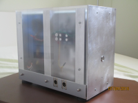
I just realized a view from the top might have been better; so here's the added pic:
Bloody nice work mate. Kudos for doing something a bit different.
Hi all,
I am a newbie here, so sorry for stupid question. 🙂
I am looking to build 4x Balanced BA-3 as pre-amp.
For this i am going to need 4pcs of BA-3 pcb, is this correct?
I am a newbie here, so sorry for stupid question. 🙂
I am looking to build 4x Balanced BA-3 as pre-amp.
For this i am going to need 4pcs of BA-3 pcb, is this correct?
Hi all,
I am a newbie here, so sorry for stupid question. 🙂
I am looking to build 4x Balanced BA-3 as pre-amp.
For this i am going to need 4pcs of BA-3 pcb, is this correct?
For 1 balanced stereo BA-3 you will need 2 PCBs.
I am thinking about trying the ba-3b as preamp. To make it fit in my existing preamp case I need to put the 10uF output caps on another board a little distance away from the rest of the circuit. Should R12 and R13 also be on that board together with the caps or should I keep them closer to the mosfets?
irrelevant
it's logical that R13 is put locally with rest of the circuit , while r12+C3 is "just" output route ..... put them wherever you want
it's logical that R13 is put locally with rest of the circuit , while r12+C3 is "just" output route ..... put them wherever you want
Thanks ZM.
I am doing a PCB with the same footprint as my UGS modules to be able to easily switch between them and then I cannot fit any 10uF film cap of decent quality at all unfortunately.
irrelevant
it's logical that R13 is put locally with rest of the circuit , while r12+C3 is "just" output route ..... put them wherever you want
I am doing a PCB with the same footprint as my UGS modules to be able to easily switch between them and then I cannot fit any 10uF film cap of decent quality at all unfortunately.
Use smaller capacitors?
Should I resist the temptation of floating one side of R3, R4, R103 and R104 and connect R3 to R104 and R4 to R103 in a X configuration ?
Wouldn't this be the same arrangement of the F5X ?
Thanks,
Davide
Wouldn't this be the same arrangement of the F5X ?
Thanks,
Davide
I think that would "short out" R5 causing a gain increase of up to 25x and probably a lot of distortion. But I recommend simulation to save time and broken parts. You should never build anything you haven't simulated first.
switchable gain?
I have happily used my BA-3b+BA-2 now since summer and with my own setup the stock gain is perfectly fine. The issue is when I try someone elses speakers or sources. Then the gain is too low. After reading around I understood that I can get more gain by basically raising R13.
I happen to have my cards made with three 1Kohm resistors in parallell at this position. Could it be made so easy that I add a switch on one of the resistors to disconnect or connect it?
Will there be an issue with the bias or offset so that these need to be adjusted each time the gain is changed this way?
just go for it
you can use pin headers with jumpers for that
or you can really use switch(es) on back or front plate
either one with 4 sections , or two with 2 sections each
no additional setting needed
you can use pin headers with jumpers for that
or you can really use switch(es) on back or front plate
either one with 4 sections , or two with 2 sections each
no additional setting needed
Thanks for the swift answer Zen Mod!
I'll go shop for some suitable switch or switches tomorrow.
I'll go shop for some suitable switch or switches tomorrow.
- Home
- Amplifiers
- Pass Labs
- Burning Amp BA-3b (Balanced)