Manual, page 2:
J2:
10 COM_RXD Input uC Control serial data out, 3.3V digital level
12 COM_TXD Output uC Control serial data in, 3.3V digital level
//
Good.
So serial data means RS232?
3.3V Digital level means TTL?
I really confused with these terminologies.
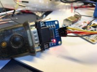
You can't connect 3.3V directly to a standard PC RS232 serial port. I guess that's what you're doing, am I correct? (taken from the "pin 5" statement. It fits with a sub-d 9 pin).
You need a TTL level serial port. Just make a search for "USB to TTL Serial Port PL2303".
You need a TTL level serial port. Just make a search for "USB to TTL Serial Port PL2303".
So this is TTL.
Why not use only one terminology?
TTL = digital level.
As in dam1021, there was RS232 and TTL.
Now in dam1121, it is the TTL at 3.3V
Why not use only one terminology?
TTL = digital level.
As in dam1021, there was RS232 and TTL.
Now in dam1121, it is the TTL at 3.3V
Good.
So serial data means RS232?
3.3V Digital level means TTL?
I really confused with these terminologies.
No, both are serial data.
It's only about signal level. TTL is 3.3V (or 5V). RS232 is RS-232 - Wikipedia
Hopefully this helps clarify:
RS232 levels: +5V ... -5V (or +/-15V)
TTL levels: 0V ... 3.3V
Serial protocol using one of the above voltage for signalling.
Best bet - buy a PL2303 chip based serial cable & connect to TTL side of the serial port.
RS232 levels: +5V ... -5V (or +/-15V)
TTL levels: 0V ... 3.3V
Serial protocol using one of the above voltage for signalling.
Best bet - buy a PL2303 chip based serial cable & connect to TTL side of the serial port.
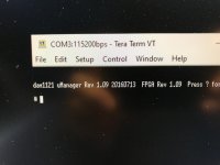
Post #1803 - the last one as of now.
//
Sorry I am new to the filter thing. Would you mind tell me more about filter?
The custom filter would (partially) overwrite some of the filters defined. There are four presets (F4, F5, F6 and F7), each filter has different frequency so there are actually many filters defined.
What you have done for post #1803 is only to overwrite the 44.1 of F4.
Is there a better organized web site (other than forum discussion thread) that shows the most common custom build filters?
Thanks!
All filters will be changed. No site. Dig into it as we all did more or less. Some site that we have posted links to for you also discuss filters.
//
//
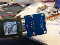
Does anybody know what the pin headers are because they are smaller than the ones on 1021, I am trying to find a better way of using the pins other than soldering?
Does anybody know what the pin headers are because they are smaller than the ones on 1021, I am trying to find a better way of using the pins other than soldering?
Those on 1021 are 2.54mm type.
Those on 1121 are 2.00mm type.
I found it's difficult to buy jump wires of 2.00mm type. Therefore I also solder on the board. I dont solder on the pins because first, it is difficult to clean solder on pin, second, I prefer to solder on the trace instead. I didn't remove the pin headers however because if I solder directly onto the trace, it might easily break the PCB is I pull the soldered wire by accident. With the header soldered onto the board, it helps to strengthen the trace.
I use similar cables than this:
40pcs in Row 40P Dupont Cable 20cm 2mm switch to 2.54mm 2P-1P wire for Arduino | eBay
40pcs in Row 40P Dupont Cable 20cm 2mm switch to 2.54mm 2P-1P wire for Arduino | eBay
- Home
- Source & Line
- Digital Line Level
- Building with the Soekris dam1121