sorry i should pay more attention to what i post, what i meant was in the manual pin 1 and 2 of j2 is +5v digital power 1 and pin 2 is +5v digital power 2 why is there x2 5 v pins so are they meant to be separately supplied?
sorry i should pay more attention to what i post, what i meant was in the manual pin 1 and 2 of j2 is +5v digital power 1 and pin 2 is +5v digital power 2 why is there x2 5 v pins so are they meant to be separately supplied?
Yes, this is mentioned in the manual, what I am doing now is to apply the same 5V power to them. I guess this is fine.
hi kenneth do yo have the resistors (traps) in place?
Sorry I don't quite understand what you mean. So I need to add a resistor(s) as well? Would you mind tell me where to place the resistor(s) and what values should that be?
Thanks!
I bought dam1121 few months ago but I could not make it sound. May I know how to make it sound?
I think you need to read the 1121 manual, specifically regarding config strap pins, which you don't appear to have considered. The relevant config pins need to be connected to ground via resistors (3K3 IIRC). My little interface board holds them in my setup.
You power supply connections look OK
Last edited:
I think you need to read the 1121 manual, specifically regarding config strap pins, which you don't appear to have considered. The relevant config pins need to be connected to ground via resistors (3K3 IIRC). My little interface board holds them in my setup.
You power supply connections look OK
Thanks bro!
I just realize that!
So just connect the resistors from strap pins to ground pin to tell it is "0"?

Thanks bro!
I just realize that!
So just connect the resistors from strap pins to ground pin to tell it is "0"?
View attachment 787069
Correct.
Maybe the attached picture will help?
https://www.diyaudio.com/forums/att...0773629t-building-soekris-dam1121-capture-jpg
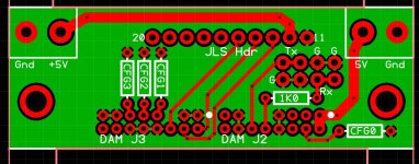
I guess it should be noted that the upper end of CFG1-3 resistors are connected to GND ... this is not visible in the PCB drawing.
Just to avoid confusion for the people struggling what to do.
Also do not forget to "Enable Audio" on J1 "EN_AUD" pin otherwise it will not give any output.
I guess it should be noted that the upper end of CFG1-3 resistors are connected to GND ... this is not visible in the PCB drawing.
Just to avoid confusion for the people struggling what to do.
Also do not forget to "Enable Audio" on J1 "EN_AUD" pin otherwise it will not give any output.
That is to connect a 3k resistor from EN_AUD to VCC5D?
Last edited:
As I have not connected my dam1121 yet I am not sure, the manual description is not really clear. It only says "PU (pull-up) when Master" 😕
According to the example drawing at the Soekris site (Test board schematics - running 2 boards as balanced) both are pulled up to 3,3 V but I guess 5 V (= supply voltage) will be fine too.
It is a bit confusing that this drawing the pin is called "MUTE" and the manual call it "EN_AUD"
So final conclusion is: pull up to supply voltage ... use VCC5A.
As I have not connected my dam1121 yet I am not sure, the manual description is not really clear. It only says "PU (pull-up) when Master" 😕
According to the example drawing at the Soekris site (Test board schematics - running 2 boards as balanced) both are pulled up to 3,3 V but I guess 5 V (= supply voltage) will be fine too.
It is a bit confusing that this drawing the pin is called "MUTE" and the manual call it "EN_AUD"
So final conclusion is: pull up to supply voltage ... use VCC5A.
Agree. It's really unclear.

What are the difference between the two VCC5D?
Are they having the same power load? (250mA)
Are they connecting to different components?
Are they having the same power load? (250mA)
Are they connecting to different components?
As the board will not work if you only connect one of the VCC5D pins I guess each pin feeds a different part of the digital circuit.
Nowhere is stated which part is fed by which pin but you need to feed them both for sure.
Nowhere is stated which part is fed by which pin but you need to feed them both for sure.
Works finally! Thanks!
View attachment 787135
Now I suggest you load my filters that I posted the other day in the "Filter Brewing" thread for a pleasant surprise! (F4 on 44,1)
//
Now I suggest you load my filters that I posted the other day in the "Filter Brewing" thread for a pleasant surprise! (F4 on 44,1)
//
Do you mean this?
Filter brewing for the Soekris R2R
Could you tell me which page exactly? Thanks
- Home
- Source & Line
- Digital Line Level
- Building with the Soekris dam1121