From the 1021 thread, in case you missed it:
‘Anyway, I have more important things to do (like adding 4K taps support to the dam1121).....’
Does ‘important’ mean we might expect it soon as against ‘in the fullness of time’, oh maestro??
We in the 1121 camp aren’t getting any younger - TNT retired since the promised update was promised - and would like the 4K taps experience before they play taps over our graves.
The aliminium plate is cut to fit exactly in vertical position in the black enclosure which I use now for the old setup.
I've used a similar approach in my DAM1121 based HPA project, which is slowly, but surely, progressing (slowness will explain the dust that is evident in some of the pictures below!).
My front panel was machined to accept the AudioZen lite control boards;

and the DAM1121 and JLSounds USB boards sit vertically behind on an aluminium plate. I chose to use the JLSounds board because I would like to use the HPA with my smartphone (running USB Audio Pro player so I play FLAC files, no MP3) as well as on the network;

As you can see, I designed a small PCB to interface the JLSounds to the DAM1121. I also have a similar arrangement for the DAM outputs and analogue power connections. For the power supplies I'm using a pair (so four power supplies) of Acko's low-noise rectifier modules.
Here's the front panel;

Eventually the DAM1121 will feed a 300B based tube headphone amp using the Transcendent Masterpice circuit. The HPA boards and all the associated power supplies take up a lot of room, hence the arrangment I chose for mounting the DAC components.

This has been a slow burn project but it's starting to come together now. Next step is to hook up the DAC components to the power supplies and test that all is well.
Maybe by the time I finish the project I'll have an immediate upgrade available in the shape of some new DAM firmware!
The Dam firmware seems to get a very hot item by now 😀
Your build is more extensive than mine I see ... and the dust too ... hahaha
Is it a DAC / HPA / Pre or do you also include the PC in the enclosure like a RPi or similar ... or is it digital in from an external streamer ?
Your build is more extensive than mine I see ... and the dust too ... hahaha
Is it a DAC / HPA / Pre or do you also include the PC in the enclosure like a RPi or similar ... or is it digital in from an external streamer ?
I've done some work on the power supplies and HPA boards over the last few days - the DAM installation has been done for a while but I didn't notice the dust until I looked at the pictures!
I'm building this to use in my 'man cave' so it is essentially a standalone system, just for headphone listening. There is no RPi or similar, instead the JLSounds I2SoverUSB board enables me to play lossless FLAC files from my smartphone or I can connect it to the USB port of an Intel NUC computer that I use as an HQPlayer NAA so I can stream music to it over the network.
Of course, the Transcendent Masterpiece can also be used as an exceptionally good pre-amp.
I might consider purchasing another DAM1121 at some point to use in my main system just as a simple DAC - for that I would use a Beaglebone Black with one of ppy's isolator/reclocker boards (I know the DAM has isolation and reclocking but the ppy board feeds a clock signal back to the BBB so it can process incoming data at its native sample rate and besides, there seems to be no disadvantage of feeding the DAM 'good quality' data) - but only if the firmware issue is resolved.
Last edited:
For the power supplies I'm using a pair (so four power supplies) of Acko's low-noise rectifier modules.
That should have read;
For the power supplies I'm using a pair (so four power supplies) of Acko's low-noise regulator modules.
Nice ... my dam1121 with BBB in one enclosure is now an “in between” build as I also want to build a full size enclosure with also a pre-amp / volume to feed the power amp.
Now I still have a seperate NAD pre-amp from which I am only using 1 input channel so a more compact DIY solution would be more convenient.
Now I still have a seperate NAD pre-amp from which I am only using 1 input channel so a more compact DIY solution would be more convenient.
Last edited:
Hi just having trouble clarifying this jumper setting , which i suspect is probably really quite simple, but could someone explain simply how to set the pins for slave and normal stereo output? the manual is confusing!
my question is my usb to i2s is galvinized so would it be benificial for me to also isolate i2s input as well?
1121 is more my taste its really accurate very pleased lead vocals in the right place and closer where it should be
diyinhk usb to i2s
I mean this card (in blue circle)
Attachments
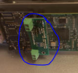
I mean this card (in blue circle)
That board features in my build;
https://www.diyaudio.com/forums/dig...-building-soekris-dam1121-63.html#post5901469
It interfaces a JLSounds I2SoverUSB board to my 1121. I set out the board and had a few fabricated.
I hope to power up my 1121 DAC this weekend so I'll find out if everything works!
one more question there are 2× 5volt digital power supplies to conect is it better to have separate or make no difference to share the same 5v for both?
one more question there are 2× 5volt digital power supplies to conect is it better to have separate or make no difference to share the same 5v for both?
If your question relates to my interface board having two terminal connector blocks, one is for the 1121 power and the other for the clean side of the JLSounds board.
I have another plug in board for the output end of the 1121 which has similar connectors for the separate +/-5V supplies it requires.
Last edited:
I bought dam1121 few months ago but I could not make it sound. May I know how to make it sound?
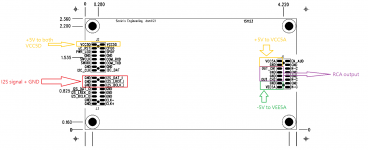
What I did is that I provided +5V to VCC5A and VCC5D, and -5V to VEE5A. Then I pass I2S signal to I2S_DAT_I, I2S_LRCK_I I2S_BCLK_I and GND. I connected RCA sockets to OUT_CH1, OUT_CH2 and GND. (see the attachment)
Is this correct?
Do I need to give separate +5v to both VCC5D and VCC5A (now they share the same power rail)
Attachments
- Home
- Source & Line
- Digital Line Level
- Building with the Soekris dam1121