Listening session
Hi Dutchman,
I am really sorry about that,
I just send you an invitation by email, your patience is rewarded. You are the first diyaudio member that can listen to the new I2S setup.
Hi Dutchman,
I am really sorry about that,
I just send you an invitation by email, your patience is rewarded. You are the first diyaudio member that can listen to the new I2S setup.
Clocking the PCM63p dac...
Hi all -
I've had this question in my mind for the past couple of days, and have just come across ur clocking-at-dac & clock-slaved-back-to-transport discussions..
{sorry, I don't mean to hijack the thread here}
If I use a Trichord clock'3' module at the Burr Brown PCM63 dacs, do I just inject the 16.9--- Mhz frequency to Bit clock / Master clock....or should it be divided down to a lesser frequency ?
As these dacs IC's are in a one-box unit {Copland 288} I have no worries about cable length back to the transport (6 inches).
I noticed that Wadia sport this kind of setup with the main clock driving the Dacs first, then linked back to slave the transport !
Many thanks for your enlightenment
(I posess very little digital knowledge- as you can tell!)
Warmest regards,
-Andy-
Doesn't Wadia use ST fiber optic cable to pass clock & signal separately between transport & dac? Curious whether ST FO transceivers (much superior to toslink) might be an interesting alternative to SPDIF or I2S. I wouldn't dismiss ST FO out of hand, tho it is less popular now than years ago. A friend of mine who was using it with his Wadia heard differences between ST cables--possibly due to variability in the quality of polishing on the cable ends.
Dave
Dave
Originally posted by Terry Demol
Personally I run a slaved transport with master oscillator in DAC. This is theoretically even better than I2S because the XO is -right at the dac- reclocking all signals. Also the interface is less important.
I also slave the CDP to DAC clock. Rather than reclocking the jittery, asynchronous signals that come out of the S/PDIF receiver, I strap the 8412/4 in mode 1 and shift the bits out of the receiver with the same clock that shifts them into the DAC chips. That way all asynchronous signal transitions are confined to the bi-phase decoder.
RE: Linear Interpolation
I did a lot of modeling, simulating, and testing of interpolation for a previous project. For NOS data streams, linear interpolation was not very rewarding. I had much better results with non-linear interpolation. I used 16 DACs per channel. The data and word clock were shifted into separate 64-bit registers and each DAC could get its data and word clock from any of the 64 taps.
Non linear interpolation
Hi Ulas,
Thanks for your reply [post524]
The 64 bit register setup for data and word clock with taps, is in the universal timing chain diagram [post#442], it already has 63 usable taps and can drive 32 DAC chips.
Read [post#151] very carefully, it already proves that I tried similar setups, but sound quality degraded, since the time interval between samples has to remain constant.
Hi NjoyTHEMUSIC,
thanks for hijaqcking this thread 🙂 [post#522]
I looked up some specs about the copland 288, it uses 8 times oversampling and a digital filter (pacific microsonics-100). So if I am not mistaken, the DAC clock equals the master clock, so it doesn't need to be divided. (44.1KHz * 48 * 8 = 16.9344 MHz)
The question about how to route the master clock is difficult to answer, each setup can have it's advantages. I think the best way to find out is just to try both setups (switch between the two if possible) and use the one that you like. A third option (since you use a short 6" cable) is locating the masterclock halfway using 2 (thin coax) cables with the same length, routed from the master clock to both DAC and transport.
cheers,
John
Ulas said:
RE: Linear Interpolation
I did a lot of modeling, simulating, and testing of interpolation for a previous project. For NOS data streams, linear interpolation was not very rewarding. I had much better results with non-linear interpolation.
What weighting did you apply to the samples?
Re: Clocking the PCM63p dac...
Two things. The PCM63 has no master clock. Dacs of its type don't. Next the PMD100 uses a burst clock and that has to be taken into account in any clock tweaking scheme.
Presumably, there is a clock that provides mclk to the PMD100 and the rest of the player. I'd try replacing that with the Trichord and leave everything else alone.
NjoyTHEMUSIC said:Hi all -
I've had this question in my mind for the past couple of days, and have just come across ur clocking-at-dac & clock-slaved-back-to-transport discussions..
{sorry, I don't mean to hijack the thread here}
If I use a Trichord clock'3' module at the Burr Brown PCM63 dacs, do I just inject the 16.9--- Mhz frequency to Bit clock / Master clock....or should it be divided down to a lesser frequency ?
As these dacs IC's are in a one-box unit {Copland 288} I have no worries about cable length back to the transport (6 inches).
I noticed that Wadia sport this kind of setup with the main clock driving the Dacs first, then linked back to slave the transport !
Many thanks for your enlightenment
(I posess very little digital knowledge- as you can tell!)
Warmest regards,
-Andy-
Two things. The PCM63 has no master clock. Dacs of its type don't. Next the PMD100 uses a burst clock and that has to be taken into account in any clock tweaking scheme.
Presumably, there is a clock that provides mclk to the PMD100 and the rest of the player. I'd try replacing that with the Trichord and leave everything else alone.
Hi ecdesigns,
Since you are planning to implement USB for the Octal DAC, here is an interesting link on different USB implementations written by John Swenson:
http://www.audioasylum.com/forums/pcaudio/messages/13336.html
Sounds complicated. How will you implement yours?
Since you are planning to implement USB for the Octal DAC, here is an interesting link on different USB implementations written by John Swenson:
http://www.audioasylum.com/forums/pcaudio/messages/13336.html
Sounds complicated. How will you implement yours?
Split the clock signal ?!!!!!?
Hi John (ecdesigns) -
Hijack ? Are you calling me 'Robin Hood' ?!?! 😉
Ah come on ....you guys are sooo 😎 , and u know it !! - That's why I came to you for help (!) 🙂
Actually...respect to you all for your kind suggestions (including Lars!)
But John, seriously.....do you have a crystal ball or something???
You even predicted (& answered) my next question - about feeding the
transport and dac stage midway !!!!! Damm ur good !
BUT- Will feeding/splitting the output clock signal from the Trichord module between the transport servo pcb and HD100 IC have any delerious effect on the integrity of the clock signal ?
I'm gonna have me some fun, and also get Elso's Kwack-7 clock to compare with the Trichord'3 ' - I'll let you know how I get on ...
L8R, -Andy-
Just FYI a similar idea for a DAC at APL in the States, involving a massive parallel array of AKM DAC chips & a 6H30 output stage.
http://www.aplhifi.com/phpBB/viewtopic.php?t=431
Dave
http://www.aplhifi.com/phpBB/viewtopic.php?t=431
Dave
USB and jitter
Hi MGH,
Thanks for your tip [post#529]
Yes as this article indicates, jitter problems can be expected from USB. Just like I already noted [post#500].
Back to the CS8412 connected close to the transport, it has jitter on BCK, I reclocked BCK, DATA and WS with the 16MHz master clock from the transport (using 2 cascaded D-flipflop for each signal) This works perfectly, when triggering the oscilloscope on the masterclock (reference), the reclocked BCK is rock solid, BCK from the CS8412 already shows jitter. So this way very low jitter I2S signals can be dereived from a jittery SPDIF interface on the transport side.
Now let's tackle the USB interface, the PCM2706 generates the jittery I2S signals just like the CS8412 did in the transport. So all that is needed is reclocking it with the "USB masterclock". To be on the safe side, a cheap USB interface add-on card is used. I got one right here from Lacie, it uses a 48MHz crystal to clock the USB host controller chip (D720101J from NEC). So we are going to do a clock mod on this card, the crystal oscillator module from this card is removed and connected to a clean 5V supply, the output signal (48MHz) is fed back to the D720101J. It is also used to drive the D-flipflops to reclock the I2S signals from the PCM2706, the USB interface can be placed very close to this USB card. Now we have a I2S low jitter signal from the USB bus.
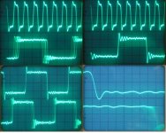
Now for the proof, reclocking can actually work, I added some oscillograms to show the effect of reclocking, I created a worst case situation with an abundance of jitter, to show it also works in extreme situations. The signals can be reclocked synchronously in this particular setup because both SPDIF and masterclock run in sync,(SPDIF signal is generated using the master clock).
Oscillogram top left: upper trace, master clock (16MC) from the mini clock upgrade, lower trace the jittery BCK. Oscilloscope is triggered on the master clock.
Oscillogram top right: Upper trace, same master clock, lower trace BCK after reclocking, spot the difference with the previous oscillogram.
Oscillogram bottom left, the oscilloscope is now EXTERNALLY triggered by the master clock, upper trace, you guessed, the reclocked BCK, lower trace, no comment needed.
Oscillogram bottom right, same signals but zoomed in using the X10 setting, still triggering externally to the master clock. In a more practical situation jitter is far less, more in the region of 300...600pS. Now a low jitter master clock is needed to further reduce jitter. To obtain very low jitter values, circuitry layout becomes very important. It's also good practice to separate both data and synchronization signals (separate chips) to avoid crosstalk were possible.
Clearly noticable is the phase shift of the reclocked BCK signal with the jittery one, this could cause sync problems, so both DATA and WS are reclocked the same way to restore phase relation, not because there were some unused D-flipflops left.
Hi MGH,
Thanks for your tip [post#529]
Yes as this article indicates, jitter problems can be expected from USB. Just like I already noted [post#500].
Back to the CS8412 connected close to the transport, it has jitter on BCK, I reclocked BCK, DATA and WS with the 16MHz master clock from the transport (using 2 cascaded D-flipflop for each signal) This works perfectly, when triggering the oscilloscope on the masterclock (reference), the reclocked BCK is rock solid, BCK from the CS8412 already shows jitter. So this way very low jitter I2S signals can be dereived from a jittery SPDIF interface on the transport side.
Now let's tackle the USB interface, the PCM2706 generates the jittery I2S signals just like the CS8412 did in the transport. So all that is needed is reclocking it with the "USB masterclock". To be on the safe side, a cheap USB interface add-on card is used. I got one right here from Lacie, it uses a 48MHz crystal to clock the USB host controller chip (D720101J from NEC). So we are going to do a clock mod on this card, the crystal oscillator module from this card is removed and connected to a clean 5V supply, the output signal (48MHz) is fed back to the D720101J. It is also used to drive the D-flipflops to reclock the I2S signals from the PCM2706, the USB interface can be placed very close to this USB card. Now we have a I2S low jitter signal from the USB bus.
Now for the proof, reclocking can actually work, I added some oscillograms to show the effect of reclocking, I created a worst case situation with an abundance of jitter, to show it also works in extreme situations. The signals can be reclocked synchronously in this particular setup because both SPDIF and masterclock run in sync,(SPDIF signal is generated using the master clock).
Oscillogram top left: upper trace, master clock (16MC) from the mini clock upgrade, lower trace the jittery BCK. Oscilloscope is triggered on the master clock.
Oscillogram top right: Upper trace, same master clock, lower trace BCK after reclocking, spot the difference with the previous oscillogram.
Oscillogram bottom left, the oscilloscope is now EXTERNALLY triggered by the master clock, upper trace, you guessed, the reclocked BCK, lower trace, no comment needed.
Oscillogram bottom right, same signals but zoomed in using the X10 setting, still triggering externally to the master clock. In a more practical situation jitter is far less, more in the region of 300...600pS. Now a low jitter master clock is needed to further reduce jitter. To obtain very low jitter values, circuitry layout becomes very important. It's also good practice to separate both data and synchronization signals (separate chips) to avoid crosstalk were possible.
Clearly noticable is the phase shift of the reclocked BCK signal with the jittery one, this could cause sync problems, so both DATA and WS are reclocked the same way to restore phase relation, not because there were some unused D-flipflops left.
Attachments
John: petje af hoor!
These oscillograms shows enought to answer my question. Triggering does the trick to show (the absense) of jitter. Very nice!
These oscillograms shows enought to answer my question. Triggering does the trick to show (the absense) of jitter. Very nice!
Re: Non linear interpolation
I’m curious; did you try every combination of 8 DACs on 64 shift register taps? There are millions of permutations. Although most random distributions of 8 or 16 DACs on 64 taps are worse than the linear one, there are a few that are very much better. I doubt you “accidentally” tried one of those before reaching your conclusion.
-ecdesigns- said:Read [post#151] very carefully, it already proves that I tried similar setups, but sound quality degraded, since the time interval between samples has to remain constant.
I’m curious; did you try every combination of 8 DACs on 64 shift register taps? There are millions of permutations. Although most random distributions of 8 or 16 DACs on 64 taps are worse than the linear one, there are a few that are very much better. I doubt you “accidentally” tried one of those before reaching your conclusion.
Changing taps
Hi Ulas,
Thanks for your reply [post#534]
No I didn't have time to try them all, since I am not retired yet 😀 . When placing taps at irregular intervals, like 0,12,24,35,45,53,59,63 the distance between each interpolated sample differs. If the time between each subsample is not the same (I used 8BCK multiples in the octal D-I DAC), you end up with a periodically varying virtual sample rate (FM modulation). Another problem is adding ripple, caused by shaping individual steps. The average virtual sample rate is also lowered, this could increase interference.
So you either use the same time between samples or you don't. Using the same time between samples is already used in the octal D-I DAC. But perhaps I missed something.
Could you explain how you connected the tabs? and why?
When placing taps at irregular intervals, like 0,12,24,35,45,53,59,63 the distance between each interpolated sample differs.
On this way Ulas wants to try to keep up with the jitter produced in his own setup used.
(sorry for the readers of this above mentioned comment from me, and possible don't know the background of it, but others who know, they understand this post completely.)
tubee said:
On this way Ulas wants to try to keep up with the jitter produced in his own setup used.
(sorry for the readers of this above mentioned comment from me, and possible don't know the background of it, but others who know, they understand this post completely.)
Do you really think the above post makes more sense knowing the background ?
Re: Split the clock signal ?!!!!!?
Dennis Moore, perhaps?
You have little choice. As things stand the clock is connected in one of two ways. The first is to the servo/decoder and then on to the PMD100 via an onboard buffered output on the main decoder chip. Before he was captured and bannished, Anticitizen One was very vocal in his disapproval of this technique.
The second sends the clock directly to the servo/decoder and the PMD100, the option I'd recommend. The Trichord should be more than capable of driving two inputs.
NjoyTHEMUSIC said:Hi John (ecdesigns) -
Hijack ? Are you calling me 'Robin Hood' ?!?! 😉
Dennis Moore, perhaps?
BUT- Will feeding/splitting the output clock signal from the Trichord module between the transport servo pcb and HD100 IC have any delerious effect on the integrity of the clock signal ?
You have little choice. As things stand the clock is connected in one of two ways. The first is to the servo/decoder and then on to the PMD100 via an onboard buffered output on the main decoder chip. Before he was captured and bannished, Anticitizen One was very vocal in his disapproval of this technique.
The second sends the clock directly to the servo/decoder and the PMD100, the option I'd recommend. The Trichord should be more than capable of driving two inputs.
John,
That is such a good physical example of jitter.
You really can imagine the hell it would play upon your desired signal.
Cheers,
Phil
That is such a good physical example of jitter.
You really can imagine the hell it would play upon your desired signal.
Cheers,
Phil
Re: Split the clock signal ?!!!!!?
Hi rfbrw ! - Thanks for the reply ...
I was hoping this was going to be the case !!! I just wanted to check, before I started hacking up the data cable in the Copland (!)
I'll make the modification (fingers crossed).
Also - I've noticed that the ac power cables that feed the servo pcb
are routed directly under the dac/analogue pcb - So, I've now used some shielded multicore cable (shield grounded) and re-routed it along the top/rear of the casework so it's nowhere near any ccts, other than where it inserts into it's designated connection point.
Thanks again ...
-Andy-
rfbrw said:
The second sends the clock directly to the servo/decoder and the PMD100, the option I'd recommend. The Trichord should be more than capable of driving two inputs.
Hi rfbrw ! - Thanks for the reply ...
I was hoping this was going to be the case !!! I just wanted to check, before I started hacking up the data cable in the Copland (!)
I'll make the modification (fingers crossed).
Also - I've noticed that the ac power cables that feed the servo pcb
are routed directly under the dac/analogue pcb - So, I've now used some shielded multicore cable (shield grounded) and re-routed it along the top/rear of the casework so it's nowhere near any ccts, other than where it inserts into it's designated connection point.
Thanks again ...
-Andy-
- Home
- Source & Line
- Digital Line Level
- Building the ultimate NOS DAC using TDA1541A