referring to the photo below

For U1,
Q0 = Q1
Q1 = Q2
Q3 = Q4 .... so on. the drawing use a different convention. I will use Q1 convention (instead of Q0)
Since CS8412 is doing 4 times, I need to get CS8412 in NOS. to get to 4x oversampling, I bent pin 9 (Q1) and short pcb pin socket pin 9 (Q1) to pin 7 (Q2). Q2 = 2.82 MHz. Which means U4 CS 8412 FCK is receiving the 2.82MHz instead of 5.64MHz. Is this correct ?
Hi ccschua,
FCK (pin13) can be used for connecting an optional 6.144 MHz external clock for providing information about source sample rate. So the 5.6488 MHz clock used here doesn't comply with the specs in the data sheet. I don't use this FCK pin and connected it to GND so it won't pick-up interference.
X1 runs at 11.2896 MHz (4 x bit clock). The actual bit clock (for NOS) is at U1 pin 7 (2.8244 MHz).
The word clock is available at U1 pin 13 (11.2896 MHz / 256 = 44.1 KHz).
So when the SAA7220 is bypassed, the DAC already runs in NOS mode (2.8224 MHz bit clock and 44.1 KHz sample rate).
So is the DI4T ready?
Seems like years since this thread started. We like to see the finished product....Pretty Please
Seems like years since this thread started. We like to see the finished product....Pretty Please
-ecdesigns- said:Hi ccschua,
FCK (pin13) can be used for connecting an optional 6.144 MHz external clock for providing information about source sample rate. So the 5.6488 MHz clock used here doesn't comply with the specs in the data sheet. I don't use this FCK pin and connected it to GND so it won't pick-up interference.
X1 runs at 11.2896 MHz (4 x bit clock). The actual bit clock (for NOS) is at U1 pin 7 (2.8244 MHz).
The word clock is available at U1 pin 13 (11.2896 MHz / 256 = 44.1 KHz).
So when the SAA7220 is bypassed, the DAC already runs in NOS mode (2.8224 MHz bit clock and 44.1 KHz sample rate).
Dear John,
reffering to that dac kit,the Hong Kong seller from ebay wrote it's specifications to be 8x oversampling,please check this link with also schematic included
http://cgi.ebay.com/Hi-End-CD-DAC-T...photoQQcmdZViewItemQQ_trksidZp1742.m153.l1262
"SPECIFICATION
1. 16 bit DAC for Hi-Fi Audio
2. S/N can attain 110dB
3. 8x oversampling frequency"
so my question would be,where from does he obtain a 2x oversampling in case we leave saa7220 in place (that does the 4x oversampling)
also check Doede's dac using a simillar reclocking circuit,he is grounding pin 13 on CS8414 just like you said
An externally hosted image should be here but it was not working when we last tested it.
ps. sorry to polute your original thread with these kind of questions

Hi MGH,
No, the DI4T is not ready, in fact design was put on halt.
It IS years since I started this thread on May 12, 2006.
This thread illustrates how difficult it is to design a high-performance DAC.
At the end of 2008, all previous developments started to produce a clearer picture of the problems involved. Next, each problem was systematically tackled, and most significant progress was made. Just when I assumed that the highly optimized (and also rather complicated) DI4T would be the "ultimate NOS DAC", and it would only be a matter of designing the final PCBs for it, the unexpected happened. The simple breadboard test set-up that was used for testing the new DI4T modules, sounded rather good. The "problem" was that the test set-up had a single TDA1543 DAC chip.
Comparison with the DI4T reference DAC left me baffled, there was little audible difference. It was a rather frustrating experience after all the hard work put into DI4T design and tuning.
The messy breadboard test set-up evolved to the messy D1M prototype. Maximum performance was squeezed out of the TDA1543 chip by using a low jitter masterclock / tracker module, a new high-performance trans-impedance I/V converter / buffer, and low noise shunt regulators. The D1M now clearly performs much better than the DI4T reference DAC.
So why not go for the much simpler, cheaper design that offers even better sound quality than my DI4T reference DAC?
So is the DI4T ready?
Seems like years since this thread started. We like to see the finished product....Pretty Please
No, the DI4T is not ready, in fact design was put on halt.
It IS years since I started this thread on May 12, 2006.
This thread illustrates how difficult it is to design a high-performance DAC.
At the end of 2008, all previous developments started to produce a clearer picture of the problems involved. Next, each problem was systematically tackled, and most significant progress was made. Just when I assumed that the highly optimized (and also rather complicated) DI4T would be the "ultimate NOS DAC", and it would only be a matter of designing the final PCBs for it, the unexpected happened. The simple breadboard test set-up that was used for testing the new DI4T modules, sounded rather good. The "problem" was that the test set-up had a single TDA1543 DAC chip.
Comparison with the DI4T reference DAC left me baffled, there was little audible difference. It was a rather frustrating experience after all the hard work put into DI4T design and tuning.
The messy breadboard test set-up evolved to the messy D1M prototype. Maximum performance was squeezed out of the TDA1543 chip by using a low jitter masterclock / tracker module, a new high-performance trans-impedance I/V converter / buffer, and low noise shunt regulators. The D1M now clearly performs much better than the DI4T reference DAC.
So why not go for the much simpler, cheaper design that offers even better sound quality than my DI4T reference DAC?
hmmm,not many people, especially design engineers that perform a business selling hi-fi equipment, would tell the truth to their customers about cheaper better sounding devices,...their marketing policy is to sell the most expensive devices with most profit even if it is a bullsh*t (generally speaking,i was not reffering to your better,more expensive product here)
so,not as if it would matter,but ecdesigns gets my whole appreciation for his remarks ! 😉
so,not as if it would matter,but ecdesigns gets my whole appreciation for his remarks ! 😉
luxury54 said:
"SPECIFICATION
1. 16 bit DAC for Hi-Fi Audio
2. S/N can attain 110dB
3. 8x oversampling frequency"
so my question would be,where from does he obtain a 2x oversampling in case we leave saa7220 in place (that does the 4x oversampling)
also check Doede's dac using a simillar reclocking circuit,he is grounding pin 13 on CS8414 just like you said
ps. sorry to polute your original thread with these kind of questions
Sorry I polute the thread here, but I can not stop to yell 'wow'. With the pin 13 of CS8412 connect to ground, the sound has open up more as if more transparent and fill with energy. It is very vicacious especially from the acoustics of Andy McKee and Allan Taylor.
Hi luxury54,
The schematic shows a single TDA1541A running in time multiplex mode I2S (pin 27 connected to VCC).
TDA1541A data sheet specifies max. bit clock frequency (fBCK) of 6.4 MHz (TDA1541A data sheet page 2), this prevents using OS rates higher than 4x using I2S (time multiplex mode).
SAA7220 data sheet specifies: The filtered data is output in I2S format at 5.6448 MHz bit rate, and a sample rate of 176.4 KHz (SAA7220 data sheet page 7).
The resulting OS factor would be 176,400 / 44,100 = 4x.
The TDA1541A can run at 8x OS when using simultaneous mode (pin 27 connected to -5V, TDA1541A data sheet page 5). Now data for both L and R channel can be clocked-in simultaneously, requiring only 16 bit clock pulses instead of 32. This would effectively double the amount of samples that can be clocked-in while staying below specified 6.4 MHz bit clock. The sample rate will then be:
5,644,800 / 44,100 / 16 = 8x.
This is also the max. sample rate for a single TDA1541A chip.
reffering to that dac kit,the Hong Kong seller from ebay wrote it's specifications to be 8x oversampling,please check this link with also schematic included
The schematic shows a single TDA1541A running in time multiplex mode I2S (pin 27 connected to VCC).
TDA1541A data sheet specifies max. bit clock frequency (fBCK) of 6.4 MHz (TDA1541A data sheet page 2), this prevents using OS rates higher than 4x using I2S (time multiplex mode).
SAA7220 data sheet specifies: The filtered data is output in I2S format at 5.6448 MHz bit rate, and a sample rate of 176.4 KHz (SAA7220 data sheet page 7).
The resulting OS factor would be 176,400 / 44,100 = 4x.
The TDA1541A can run at 8x OS when using simultaneous mode (pin 27 connected to -5V, TDA1541A data sheet page 5). Now data for both L and R channel can be clocked-in simultaneously, requiring only 16 bit clock pulses instead of 32. This would effectively double the amount of samples that can be clocked-in while staying below specified 6.4 MHz bit clock. The sample rate will then be:
5,644,800 / 44,100 / 16 = 8x.
This is also the max. sample rate for a single TDA1541A chip.
I never learn this in university, but the audio university.
All this while, I thought I was running at 8x which is printed at the manufacturer website. I am totally wrong. So it sounds like tda1541a running in 4x is quite balance.
To do 8x, I need to bend pin 27 of TDA1541a and solder it to -5V.
Then can I know how to connect the SAA 7220 to TDA1541a ? I need to use DOBM to output 32bit word to pin 3 and pin 4 ? any other changes as per the schematic.
Hi John,
I was waiting for the arrival of the DI4. Have been hunting for
the 1541s & now this post. Hmmm. Hey, maybe single 1541
would sound better then the 1543. Have you tried it ?
Thanks
I was waiting for the arrival of the DI4. Have been hunting for
the 1541s & now this post. Hmmm. Hey, maybe single 1541
would sound better then the 1543. Have you tried it ?
Thanks
Thanks again John for your answer about 8x OS,
it seems like that seller is sending out fake info about his products 😕
I was very curious about the sound impression with your TDA1543 implementation and took out from the closet an ancient Philips AK-601 that does make the conversion through this IC.
(i was keeping it only for a spare CDM4/19 transport)
it seems that it is in 4x OS mode fed from a Mitsubishi m50423fp decoder...
It has a very bad implementation of the analog stage after the TDA1543 with a NE5532 Opamp,it sounds very muddy, no punch,no dynamics...
so i was searching to raise it's voltage to 8V insted of 5V and add some passive I/V conversion using this TDA1543 calculator from this posting http://www.diyhifi.org/forums/viewtopic.php?t=104 and after that a SRPP tube stage using a 6N2P just like here
changing of course the I/V resistor value :

Do you think is it worth a try?
Thanks.
it seems like that seller is sending out fake info about his products 😕
I was very curious about the sound impression with your TDA1543 implementation and took out from the closet an ancient Philips AK-601 that does make the conversion through this IC.
(i was keeping it only for a spare CDM4/19 transport)
it seems that it is in 4x OS mode fed from a Mitsubishi m50423fp decoder...
It has a very bad implementation of the analog stage after the TDA1543 with a NE5532 Opamp,it sounds very muddy, no punch,no dynamics...
so i was searching to raise it's voltage to 8V insted of 5V and add some passive I/V conversion using this TDA1543 calculator from this posting http://www.diyhifi.org/forums/viewtopic.php?t=104 and after that a SRPP tube stage using a 6N2P just like here
changing of course the I/V resistor value :
Do you think is it worth a try?
Thanks.
ccschua said:To do 8x, I need to bend pin 27 of TDA1541a and solder it to -5V. Then can I know how to connect the SAA 7220 to TDA1541a ?
You can't. 7220 is 4x and I2S, period.
Going to 8x requires a different filter, e.g. pmd100. Then you can use 8x, but it also requires glue logic.

-ecdesigns- said:
The "problem" was that the test set-up had a single TDA1543 DAC chip.
Comparison with the DI4T reference DAC left me baffled, there was little audible difference. It was a rather frustrating experience after all the hard work put into DI4T design and tuning.
The messy breadboard test set-up evolved to the messy D1M prototype. Maximum performance was squeezed out of the TDA1543 chip by using a low jitter masterclock / tracker module, a new high-performance trans-impedance I/V converter / buffer, and low noise shunt regulators. The D1M now clearly performs much better than the DI4T reference DAC.
Do you want to say that you quit the linear interpolation ?
😀 It alters the waveform 😀

Hi JC951t,
Yes I did, it does sound slightly better than the DI4T by the way, but I have to say that the prototype set-up is not optimized yet. I still have to try the new high-performance trans-impedance converter / buffer, and the new current source / shunt regulators.
So you could already have better performance than the DI4T, using a single TDA1541A-based DAC. Cost would be a lot lower too.
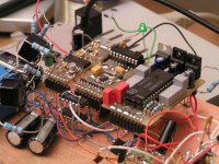
I attached a picture of this single-TDA1541A prototype using an early trans-impedance I/V converter. It runs on a single small transformer, requires no tubes, and only consumes a few watts.
It's based on 3 small modules, the one at the left is the CS8416-based SPDIF receiver module. The one in the center is the master clock / tracker / buffer module. This one will be replaced by the multi-frequency tracker module that supports up to 96 KHz sample rate. The one on the right is the new TDA1541A module with on-board differential DEM clock circuit and I2S attenuators.
As you can see, I almost completed all required modules for the TDA1541A-based DAC.
I was waiting for the arrival of the DI4. Have been hunting for
the 1541s & now this post. Hmmm. Hey, maybe single 1541
would sound better then the 1543. Have you tried it ?
Yes I did, it does sound slightly better than the DI4T by the way, but I have to say that the prototype set-up is not optimized yet. I still have to try the new high-performance trans-impedance converter / buffer, and the new current source / shunt regulators.
So you could already have better performance than the DI4T, using a single TDA1541A-based DAC. Cost would be a lot lower too.
I attached a picture of this single-TDA1541A prototype using an early trans-impedance I/V converter. It runs on a single small transformer, requires no tubes, and only consumes a few watts.
It's based on 3 small modules, the one at the left is the CS8416-based SPDIF receiver module. The one in the center is the master clock / tracker / buffer module. This one will be replaced by the multi-frequency tracker module that supports up to 96 KHz sample rate. The one on the right is the new TDA1541A module with on-board differential DEM clock circuit and I2S attenuators.
As you can see, I almost completed all required modules for the TDA1541A-based DAC.
Attachments
Oh! John...it was very hard for me to go down from 16DAC chips to only 4! 🙁 😀
I think I can't go down again to only one chip
Maybe we can put a DAC tower there instead
Maybe the key step was the charge transfer supply?
Another topic; your experiment with a high voltage output DAC, with a variable I/V resistance (if I recall well) to feed directly some speakers, keeps doing circles in my mind...yesterday I saw a "webinar" from Analog Devices about Digital Pots. They have some digipots made of thin film resistors with 0.1% tolerance and 35ppm tempco!
I don't know if they suit this the prototype but they sound interesting. I'm sure they shall make very good preamps (if they lack internal opamps).
Cheers,
M
-ecdesigns- said:Hi JC951t,
Yes I did, it does sound slightly better than the DI4T by the way, but I have to say that the prototype set-up is not optimized yet. I still have to try the new high-performance trans-impedance converter / buffer, and the new current source / shunt regulators.
So you could already have better performance than the DI4T, using a single TDA1541A-based DAC. Cost would be a lot lower too....
Hello John
Good if only one tda1541 could do the job, cost less, but what about the 44 khz output filtering ?
Thank
Bye
Gaetan
I'm speechless...only one 1541A chip? What am I going to do with the other 9 chips I have? And no tubes? Tell me it aint so...Me loves boobes, I mean tubes.
Hi Bernhard,
I just said that the D1M (with a single DAC chip, NOS) managed to outperform the DI4T.
This could have various causes like lower jitter sensitivity (173ps), lower master clock load (only one DAC chip instead of 4), or the new trans-impedance I/V converter / buffer that has large bandwidth and fully meets TDA154x 25mV ac output compliance. Finally the D1M runs on shunt regulators, powered by cascoded-cascode current sources.
Given a certain amount of master clock jitter, the DAC with lowest jitter sensitivity would perform best, provided clock jitter is the main reason for sound quality degradation. The single DAC chip also enables to locate it very close to the master clock, keeping bit clock interlink as short as possible.
The trans-impedance I/V converter / buffer uses no active amplification. By meeting TDA154x 25mV output compliance, distortion introduced by ac voltages across the diode-transistor bit switches inside the DAC chip are minimized. Other advantage of the trans-impedance converter is that the TDA1543 can now run on minimum power supply as specified in the data sheet (3V). This reduces on-chip ground-bounce.
The low noise power supplies that have a high series impedance (few mega-Ohms) that connects to the unregulated / polluted power supply, and a very low shunt impedance (< 0.2 Ohms) across the load, will effectively isolate connected loads from power supply noise and interference.
Yes it does.
Do you want to say that you quit the linear interpolation ?
I just said that the D1M (with a single DAC chip, NOS) managed to outperform the DI4T.
This could have various causes like lower jitter sensitivity (173ps), lower master clock load (only one DAC chip instead of 4), or the new trans-impedance I/V converter / buffer that has large bandwidth and fully meets TDA154x 25mV ac output compliance. Finally the D1M runs on shunt regulators, powered by cascoded-cascode current sources.
Given a certain amount of master clock jitter, the DAC with lowest jitter sensitivity would perform best, provided clock jitter is the main reason for sound quality degradation. The single DAC chip also enables to locate it very close to the master clock, keeping bit clock interlink as short as possible.
The trans-impedance I/V converter / buffer uses no active amplification. By meeting TDA154x 25mV output compliance, distortion introduced by ac voltages across the diode-transistor bit switches inside the DAC chip are minimized. Other advantage of the trans-impedance converter is that the TDA1543 can now run on minimum power supply as specified in the data sheet (3V). This reduces on-chip ground-bounce.
The low noise power supplies that have a high series impedance (few mega-Ohms) that connects to the unregulated / polluted power supply, and a very low shunt impedance (< 0.2 Ohms) across the load, will effectively isolate connected loads from power supply noise and interference.
It alters the waveform
Yes it does.
Hi maxlorenz,
Imagine how I felt when the D1M outperformed the DI4T that has cost me so much time, effort, and money to build. On the other hand, there is the review from my latest demonstration in Velsen Holland. I promised to let you know when the review was on their website, well here it is:
http://acv.hifi.nl/
Review is under "Verslag" , "Naar verslag november 2008".
You might use an online translator, or use Google translate. I translated the part that describes the audio set performance, and will just quote it here. But I suggest to have the original text, posted on their website translated correctly.
Quote "
"After a 20 minutes introduction, he starts with a track of Diana Krall. I am sitting in the back of the room. First impression is an extremely fast and accurate sound. The sound stage is enormous. But bass is rather dominating. There is a bit too much pressure, and bass isn't tight enough for my taste. The voice of Diana Krall does sound natural as it's supposed to be. The piano also reverberates for a very long time. That's a sign that micro information is ok. This is usually a result of good electronics.
The presented sound stage is overwhelmingly large. Because the speakers act like omni-directional emitters, the sound stage is rather different. During the demo this feeling remains, but then, we are used to listen to the sound stage from direct emitters. This routine isn't easily adjusted during one evening of listening. I am not sure if I could get used to it. What I can say is that sound is a lot more beautiful after the break, I then moved to the front of the room, and there the sound is dramatically different. Bass is much more controlled, and therefore the tonal balance is simply a lot better. The tonal balance remains a bit analytical to my taste, as a listener, not a single detail will pass unnoticed. But this never gets tiring during the entire demo, but I personally prefer a bit warmer sound. Besides, it's the design goal of EC designs to produce as realistic sound as possible within the limitations of the recorded material, without causing listening fatigue. Mission accomplished I would say. John later adds that the demo would have provided a more familiar sound when using good conventional speakers. He is aware that it requires some time to get used to the sound of the sonic resonators.
Another test is performed using a smaller DAC version, the DI4MJ. ...... The larger one provides better bass, and is more precise in general, but personally I think the smaller DAC sounds more natural using this set. I prefer this one, despite the fact it's much cheaper. This is a result of a more relaxed tonal balance, and that is what I prefer, despite better qualities of the larger DAC".
No, too many bit clock loads, and too much I2S signal interference.
The D1M runs on a cheap 3 watts external mains adapter without charge-transfer circuits.
This configuration works with moderate output voltages across the I/V resistor (limited power provided by the single DAC chip). Since there is no attenuation (variable I/V resistor), sound is really crystal clear, free of distortion and noise that's so typical with subsequent attenuation (volume control), and amplification (power amp).
If 10 ... 20 watts rms is sufficient, this is a super solution. You just have to include protection circuits to prevent loud pops or clicks during power-up, power-down, and when using resistors and switches for varying I/V resistor value.
When using a single TDA1543, you will need approx. 12K Ohm I/V resistor for 10W rms, and approx. 24K Ohm resistor for 20W rms (using a unity-gain power buffer). The use of the trans-impedance stage is required here, so TDA1543 25mVpp output compliance is fully met.
Oh! John...it was very hard for me to go down from 16DAC chips to only 4!
Imagine how I felt when the D1M outperformed the DI4T that has cost me so much time, effort, and money to build. On the other hand, there is the review from my latest demonstration in Velsen Holland. I promised to let you know when the review was on their website, well here it is:
http://acv.hifi.nl/
Review is under "Verslag" , "Naar verslag november 2008".
You might use an online translator, or use Google translate. I translated the part that describes the audio set performance, and will just quote it here. But I suggest to have the original text, posted on their website translated correctly.
Quote "
"After a 20 minutes introduction, he starts with a track of Diana Krall. I am sitting in the back of the room. First impression is an extremely fast and accurate sound. The sound stage is enormous. But bass is rather dominating. There is a bit too much pressure, and bass isn't tight enough for my taste. The voice of Diana Krall does sound natural as it's supposed to be. The piano also reverberates for a very long time. That's a sign that micro information is ok. This is usually a result of good electronics.
The presented sound stage is overwhelmingly large. Because the speakers act like omni-directional emitters, the sound stage is rather different. During the demo this feeling remains, but then, we are used to listen to the sound stage from direct emitters. This routine isn't easily adjusted during one evening of listening. I am not sure if I could get used to it. What I can say is that sound is a lot more beautiful after the break, I then moved to the front of the room, and there the sound is dramatically different. Bass is much more controlled, and therefore the tonal balance is simply a lot better. The tonal balance remains a bit analytical to my taste, as a listener, not a single detail will pass unnoticed. But this never gets tiring during the entire demo, but I personally prefer a bit warmer sound. Besides, it's the design goal of EC designs to produce as realistic sound as possible within the limitations of the recorded material, without causing listening fatigue. Mission accomplished I would say. John later adds that the demo would have provided a more familiar sound when using good conventional speakers. He is aware that it requires some time to get used to the sound of the sonic resonators.
Another test is performed using a smaller DAC version, the DI4MJ. ...... The larger one provides better bass, and is more precise in general, but personally I think the smaller DAC sounds more natural using this set. I prefer this one, despite the fact it's much cheaper. This is a result of a more relaxed tonal balance, and that is what I prefer, despite better qualities of the larger DAC".
Maybe we can put a DAC tower there instead
No, too many bit clock loads, and too much I2S signal interference.
Maybe the key step was the charge transfer supply?
The D1M runs on a cheap 3 watts external mains adapter without charge-transfer circuits.
Another topic; your experiment with a high voltage output DAC, with a variable I/V resistance (if I recall well) to feed directly some speakers, keeps doing circles in my mind...yesterday I saw a "webinar" from Analog Devices about Digital Pots. They have some digipots made of thin film resistors with 0.1% tolerance and 35ppm tempco!
I don't know if they suit this the prototype but they sound interesting. I'm sure they shall make very good preamps (if they lack internal opamps).
This configuration works with moderate output voltages across the I/V resistor (limited power provided by the single DAC chip). Since there is no attenuation (variable I/V resistor), sound is really crystal clear, free of distortion and noise that's so typical with subsequent attenuation (volume control), and amplification (power amp).
If 10 ... 20 watts rms is sufficient, this is a super solution. You just have to include protection circuits to prevent loud pops or clicks during power-up, power-down, and when using resistors and switches for varying I/V resistor value.
When using a single TDA1543, you will need approx. 12K Ohm I/V resistor for 10W rms, and approx. 24K Ohm resistor for 20W rms (using a unity-gain power buffer). The use of the trans-impedance stage is required here, so TDA1543 25mVpp output compliance is fully met.
-ecdesigns- said:
No, too many bit clock loads, and too much I2S signal interference.
When I tried to drive 8 paralleled bit clock inputs over a longer distance directly from CS8412, there was a crackling noise and 330 ohm termination was needed to avoid that.
With my opamp based clock buffer it works well without termination.
- Home
- Source & Line
- Digital Line Level
- Building the ultimate NOS DAC using TDA1541A