How do you do
Hiii ECSDESIGN
Im just a newbee
Me and my friend interested to build your DACS
just to add our personal equipment not for trade
Now we trying to save our money to build your board
We have been collected TDA1541a, opa627bp, lm4562
just a little question, maybe you can help me
- what kind of tube you use in your dacs, what type
and what number (never use tube before)
- I hear that different tube have different sound colour
do you have tasted it with other tube
- what the other tube your suggest and your dacs
still work great
thank you ecsdesign, great dacs ... great R & D
regards, jeffry
Hi jeffry_widjaja,
First I will explain how the DI8M I/V output stage works,
There are 2 Op-amp I/V stages for each channel (4 in total). I use LM4562 that's forced into class A operation and includes the new noise-gain manipulation circuit. The I/V stage is used to drive two differential to single-ended / buffer stages.
Differential to single-ended buffer stage #1 is based on the LM4562 OP-amp, forced into class A operation, and including the noise-gain manipulation circuit.
Differential to single-ended buffer stage #2 is based on a ECC83S (differential input stage) and ECC82 (cathode follower, two triodes in parallel)
The outputs of both differential stages are then summed / attenuated by a resistive output attenuator. OP-amp : tube = 2 : 1, so the OP-amp output signal dominates.
The reasons for using two differential to single-ended stages in parallel is to achieve an optimal balance between odd and even harmonics, and take advantage of local feedback and the absence of thermal memory distortion in the tube differential to single-ended / buffer stage.
I use JJ electronics factory selected, balanced / matched ECC82 / ECC83S tubes with gold-plated pins and grid.
Yes tubes can produce different sound colour, so I had to select tubes that produced the most neutral / transparent sound.
square wave
Just a question Ecdesigns:
How does your DAC reproduce a square wave?
Ringing or no-ringing?
Thx!
Just a question Ecdesigns:
How does your DAC reproduce a square wave?
Ringing or no-ringing?
Thx!
-ecdesigns- said:Hi QSerraTico_Tico,
DI DACs have zero ringing (linear interpolation / no analogue filtering)
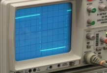
can you show scope picture?
Hi John,
I think I found a couple of references 😉 Will try ASAP...
Cheers,
M
I use LM4562 that's forced into class A operation and includes the new noise-gain manipulation circuit.
I think I found a couple of references 😉 Will try ASAP...
Cheers,
M
Yes, I was wondering what causes those "steps" or glitches.maxlorenz said:We can see 8 "steps" or spots on the vertical lines 😉
Your scope is cuter than mine 🙂
QSerraTico_Tico said:
Yes, I was wondering what causes those "steps" or glitches.
you seem to have no idea how this DAC idea works
if you read the thread all will be revealed
even in the first few pages it is explained very well
mike
mikelm said:
you seem to have no idea how this DAC idea works
if you read the thread all will be revealed
even in the first few pages it is explained very well
mike
thx 😉
Hi QserraTico_Tico,
These are interpolated samples, placed between the original samples (DI8M has 352.8 KHz output sample rate).
The sample amplitude is also interpolated, so each single amplitude step is now subdivided in 8 equal smaller steps. That's why the 1 KHz square wave transients are subdivided in 8 smaller steps.
The interpolation method used, provides a slow rolloff linear phase filter
Yes, I was wondering what causes those "steps" or glitches.
These are interpolated samples, placed between the original samples (DI8M has 352.8 KHz output sample rate).
The sample amplitude is also interpolated, so each single amplitude step is now subdivided in 8 equal smaller steps. That's why the 1 KHz square wave transients are subdivided in 8 smaller steps.
The interpolation method used, provides a slow rolloff linear phase filter
Hi maxlorenz,
This link might be helpful:
http://www.analog.com/Analog_Root/s...ols/interactiveTools/stability/stability.html
Look for noise-gain manipulation.
The idea is to achieve improved negative feedback loop stability.
This can be achieved by placing a resistor between the OP-amp inverting and non-inverting inputs (RD). I settled for approx. 5 times the feedback resistor value for RD (best subjective sound quality).
DI8(M) I/V resistors are 500R, so RD would be approx. 2K5.
DI16 I/V resistors are 475R, so RD would be approx. 2K37
DI16 (8*4) I/V resistors are 237R, so RD would be approx. 1K18
Diff amp feedback resistors are 1K96, so RD would be approx. 10K
The tubediff amp required no correction as it uses local feedback.
I think I found a couple of references Will try ASAP...
This link might be helpful:
http://www.analog.com/Analog_Root/s...ols/interactiveTools/stability/stability.html
Look for noise-gain manipulation.
The idea is to achieve improved negative feedback loop stability.
This can be achieved by placing a resistor between the OP-amp inverting and non-inverting inputs (RD). I settled for approx. 5 times the feedback resistor value for RD (best subjective sound quality).
DI8(M) I/V resistors are 500R, so RD would be approx. 2K5.
DI16 I/V resistors are 475R, so RD would be approx. 2K37
DI16 (8*4) I/V resistors are 237R, so RD would be approx. 1K18
Diff amp feedback resistors are 1K96, so RD would be approx. 10K
The tubediff amp required no correction as it uses local feedback.
Excellent!
Now all I have to do is figure out what "phase", "phase margin" ...etc, means 😀
(is 78° phase margin good?)
M
Now all I have to do is figure out what "phase", "phase margin" ...etc, means 😀
(is 78° phase margin good?)
M
maxlorenz said:(is 78° phase margin good?)
Yes - it means the circuit is very stable
If the phase margin is low it means a circuit ( with feedback ) tends towards ringing, instablilty & ultimately oscillation.
The tendency for ringing can make the circuit sound rough.
Thanks, Mikelm, I will try this mod everywhere as it seems easy and cheap. May be even better than class A? (which uses 2 difficult to find J-Fets + 1R 😡 )
For chipamps, and RC network with a cap "as big as feasible" (quoted) will do?
Cheers,
M
For chipamps, and RC network with a cap "as big as feasible" (quoted) will do?
Cheers,
M
OK, I am new on this forum and I have read some of the pages on this subject...
Interesting aproach and dedication to the ideea.
So, if I got it right, in the case of using 8 DAC's, for the first 8 samples, you got one DAC outputting the signal, for the next 8 you got another DAC putting the same current (thus doubling the voltage drop on the resistor), and so on til you got all 8 DAC's outputting the same value on the resistor - so it is multiplied by 8, you got the extra 8 steps in the time domain.
BUT, this is not exactly how regular oversamplig interpolation works, just done low-tech?
The regular interpolation takes the two succesive values of the signal and makes 8 linear steps (OS) in that time frame. It is added dithering to the "extra bits" because the "added" bits are anyway fake bits and for harmonics sake, a "noisy" line between the 2 original samples is better than a "straight" line (like yours). It is reducing the 3-rd harmonic by spreading it to the odd and even harmonics in an non-recurring pattern. I guess sounds better to the brain, that's why it is done so...
PS: It is like having a moire image on your PC screen. If it is constant in the same position becomes annoying. If the same pattern moves really fast everywhere, your eyes will see some fuzzines but will be less annoying. My 2 cents here... maybe I am wrong.
Hi,
To ensure a mean 0V DC level at the output has anyone thought about using a DC servo instead of a coupling cap but one with a twist - one that adjusts the 2mA current source biasing the DAC output rather than simply cancelling the offset at the buffer opamp ? Would adjusting the current source increase distortion ?
Cheers,
Jon
- Home
- Source & Line
- Digital Line Level
- Building the ultimate NOS DAC using TDA1541A