I will fight distorsion figures also on my setup. Starting with the hugely distorting speakers, will build them soon. There is a way to limit distorsion in a dac: OS  😀
😀
😀Hi Soundcheck and Bernhard,
OT again, from http://www.stevens-billington.co.uk/page102.htm
"In some cases the presence of a large section of unloaded secondary may cause an ultrasonic peak to appear in the response. How much of a problem this represents depends upon many factors. If this is encountered as a problem the simple solution is to provide a series RC Circuit (snubber), which is connected between the 0db attenuation Tap and the output of the switch. Suitable Values should be determined by lab-testing and listening tests."
I tried before "by ear" some RC values and did not get any improvement, obviously. Now that I have a scope I finally should get rid of this ultrasonic pEAk 😀
RC from 0 att. to "output"...don't drop your TVC cheap, Klaus...
(or maybe I could use it for a multichannel preamp 😀 )
Next week, more DI16 tweaks, I hope
maxlorenz said:
a large section of unloaded secondary may cause an ultrasonic peak to appear in the response
Every audio transformer has a bad impulse and frequency response without loading, it shows ringing.
All can be eliminated by a resistor or RC from output to ground ( TVC: 0dB tap to ground ) if overloaded, the rise time will be limited and give a falling frequency response.
Best feed the primary with a clean 1k square , watch with a scope and adjust with a 20 k pot on secondary so that there is no overshoot, replace with fixed resistor then.
47-100k on amp input is not enough.
Coming back to my earlier calculations, related to Rref.
I made a small mistake in my conclusions. 🙄
Doede's dimensioning is matching pretty much the theoretical
calculations I made. Sorry for that confusion.
I got a 120R on one of each 12Dac Tower ending up at 60R AsIs vs. 66R theoretical on 24Dacs. That's why it works. 😉
MaxLorenz:
Did you try direct connecting your Amp yet? 😉 It doesn't cost you anything. Except that you need to write-off your TVC. 😀
Spent some time on this. Because, I won't spent any on TX102 😀 Would be interesting to discuss this with you guys.
Multichannel with a PC control is even better. Timing and levels can easily be adjusted.
Bernhard said:
Every audio transformer has a bad impulse and frequency response without loading, it shows ringing.
All can be eliminated by a resistor or RC from output to ground ( TVC: 0dB tap to ground ) if overloaded, the rise time will be limited and give a falling frequency response.
Best feed the primary with a clean 1k square , watch with a scope and adjust with a 20 k pot on secondary so that there is no overshoot, replace with fixed resistor then.
47-100k on amp input is not enough.
BTW. Did you try to run your TVC in autotransformer-mode?
(in case you run unbalanced)
Hi folks.
I'd just like to share my findings on replacing Rref on a 1543.
I also put a 0,1uf BG-NX in parallel to Rref as mentioned by Doede.
DDDAC stock was a 120R type per 12 DACs.
I now replaced it with one 60R Econistor 0.01% from Rhopoints
for 24Dacs.
A bit of background: all my stacked DACs (2*12) are connected pin-by-pin via one single silver-wire to improve the signal path of multiple soldering joints from top to bottom of the tower.
My outputs are also taken off the middle of the towers with silver wires to get a close to symmetric wiring, when connecting the different DAC boards.
Otherwise, using the standard DDDAC connections, from the top of one tower to the other towers I/V-resistor you'd face almost 6- 7inches difference and 15 soldering joints.
The new Rref and my I/V-Rs are now directly connected to my star ground.
Now what happend: To make it short - A lot. 😀 Definetly more compared to replacing the Riken against the Econistors as I/V-R.
The sound improved in all aspects again. Most impressive were the
sudden added 3dimensionality, dynamics and resolution. A grand piano sounds even more realistic now. And so on - And so on.
It seems that the Rrefs have been a kind of bottleneck all the time.
But it's obvious, isn't it - It's the current for I/V-R which runs through these Rrefs.
I just can recommend to all the DDDACers ( or 1543DACers) around here. Place your order today! This was just a 5 pound tweak. 😉
"100% sound quality" is quite a relative term, isn't it. 😉 The race goes on.
It's fun to be around here folks!
Cheers
Rref:
Dear John, what if we connect a small inductor in series with Rref instead of a cap in parallel?
TeddyReg:
Putting a TeddyReg on DDDAC's Tower made the same kind of improvement in sound that it made on DI16 DAC circuit: softer, more elegant, more extended and refined. The LT1085 based Te ddyReg fell from 8,45 to 7,6V though...I'll play with some R to improve it. I can't say I hear something bad from this.
I'll try to add a TeddyReg for the 15V output section of the DI16 this week, plus a secret tweak 😉
Cheers,
M
Passive I/V conversion
Hi soundcheck,
Rhopoint wirewound resistors offer lower noise than metal film, but they still don't meet all important requirements for passive I/V resistors:
1) Lowest possible noise.
2) Non-inductive.
3) Conductive material should have best possible electrical conductivity (copper / silver).
The I/V resistor should be just that, a pure (non-inductive) resistor. Rhopoint resistors have poor construction (two counter-wound inductors), this is really not the best way to create a true non-inductive winding. Mobius loops are better.
It's obvious that when attempting to achieve good SN ratio with passive I/V, low noise resistors are of the utmost importance. When using passive I/V, it's best to use a differential configuration in order to attenuate common noise, it also provides twice the output voltage without increasing ac voltage at each DAC (group).
This may sound odd, but after a lot of experimenting, it turns out that best I/V resistor performance is achieved when using materials with the highest electrical conductivity (copper / silver wire). Despite equal resistivity, NiCr wirewound resistors produce more grain and less resolution than a copper wire passive I/V resistor.
I now use passive I/V resistors that meet requirements 1 ...3, non-inductive copper wire resistors (39R).
The ultimate passive I/V resistors would be non-inductive pure silver wire resistors.
I really wasn't a big fan of passive I/V (TDA154X ouput compliance), but since I arrived at a dead-end with OP-amps and OP-amp I/V conversion, I decided to give passive I/V conversion another chance.
First I measured THD @ 1KHz (to see what really happens when output compliance is exceeded by a large margin).
It turned out that it wasn't nearly as bad as the datasheet suggests, THD rapidly increases above a certain threshold, below this threshold THD only increases marginally. I arrived at the following values (optimum between SN ratio and THD):
TDA1543: 500mVpp (@ 5V), THD 0.02%
TDA1541A: 320mVpp, THD 0.002%
4 x TDA1543 differential 2 x 500mVpp (@ 5V), THD 0.01%
4 x TDA1541A differential 2 x 320mVpp, THD 0.001%
These are average THD values, and include THD of the attached diff. amp. THD can differ due to component tolerances. I was able to achieve 0.003% THD @ 1 KHz with 4 x TDA1543 (Taiwan), differential passive I/V, and a discrete JFET diff. amplifier.
Recent tests with passive I/V conversion and modified tube diff. amp. turned me into a passive I/V fan . No more (discrete) OP-amp I/V converters for me.
Meanwhile the DI8M reference DAC is no more , it's now replaced by a DI4T (4 x TDA1541A, differential passive I/V, tube-only diff. amp, discrete VCXO directly driving the 4 DAC chips, no reclocker).
Hi soundcheck,
I now replaced it with one 60R Econistor 0.01% from Rhopoints
Rhopoint wirewound resistors offer lower noise than metal film, but they still don't meet all important requirements for passive I/V resistors:
1) Lowest possible noise.
2) Non-inductive.
3) Conductive material should have best possible electrical conductivity (copper / silver).
The I/V resistor should be just that, a pure (non-inductive) resistor. Rhopoint resistors have poor construction (two counter-wound inductors), this is really not the best way to create a true non-inductive winding. Mobius loops are better.
It's obvious that when attempting to achieve good SN ratio with passive I/V, low noise resistors are of the utmost importance. When using passive I/V, it's best to use a differential configuration in order to attenuate common noise, it also provides twice the output voltage without increasing ac voltage at each DAC (group).
This may sound odd, but after a lot of experimenting, it turns out that best I/V resistor performance is achieved when using materials with the highest electrical conductivity (copper / silver wire). Despite equal resistivity, NiCr wirewound resistors produce more grain and less resolution than a copper wire passive I/V resistor.
I now use passive I/V resistors that meet requirements 1 ...3, non-inductive copper wire resistors (39R).
The ultimate passive I/V resistors would be non-inductive pure silver wire resistors.
I really wasn't a big fan of passive I/V (TDA154X ouput compliance), but since I arrived at a dead-end with OP-amps and OP-amp I/V conversion, I decided to give passive I/V conversion another chance.
First I measured THD @ 1KHz (to see what really happens when output compliance is exceeded by a large margin).
It turned out that it wasn't nearly as bad as the datasheet suggests, THD rapidly increases above a certain threshold, below this threshold THD only increases marginally. I arrived at the following values (optimum between SN ratio and THD):
TDA1543: 500mVpp (@ 5V), THD 0.02%
TDA1541A: 320mVpp, THD 0.002%
4 x TDA1543 differential 2 x 500mVpp (@ 5V), THD 0.01%
4 x TDA1541A differential 2 x 320mVpp, THD 0.001%
These are average THD values, and include THD of the attached diff. amp. THD can differ due to component tolerances. I was able to achieve 0.003% THD @ 1 KHz with 4 x TDA1543 (Taiwan), differential passive I/V, and a discrete JFET diff. amplifier.
Recent tests with passive I/V conversion and modified tube diff. amp. turned me into a passive I/V fan
. No more (discrete) OP-amp I/V converters for me.Meanwhile the DI8M reference DAC is no more
, it's now replaced by a DI4T (4 x TDA1541A, differential passive I/V, tube-only diff. amp, discrete VCXO directly driving the 4 DAC chips, no reclocker).Hi all
Still following the thread with great interest. Due to my lack of knowledge on active IV combined with the love for valves I was already poundering the use of passive IV fed into a differential tube stage for a while (to use with the current outputs of the DI8M). I am specially thinking about an Aikido like amplifying stage, since Broskie has shown an implementation for balanced DAC's... and now it seems that John (the DI8M designer, not Broskie) himself is also going for this approach!
I would like to add an additional question, related to the regulators for the DI8M. The board is actually fed from +8V / -8V and -20V, that are then further regulated to the final voltages for the ICs. If one uses some very special (low ripple) regulators for the +8V / -8V and -20V (I am thinking about something along the lines of this regulator (first page, with the TL431, Opamp and transistor), the ripple will be minimal. My question...the regulators on the individual TDA1541A boards have worse ripple performance, but once they are fed with a very low ripple voltage, I believe they will only help reducing this ripple further?
John, in some weeks I expect to receive money from the 'belastingdienst', and then I will go an buy your boards.
Erik
Hi maxlorenz,
Yes this might work. You could also try a JFET constant current source instead of a reference current resistor (DDDAC). However, I got best results wit VREF pins unconnected, using a clean external 2.5V reference voltage.
The Teddyreg caused a voltage drop, this makes it difficult to say if the improvement was caused by a voltage drop or reduced ripple current, or perhaps both.
Perhaps the voltage drop could be reduced by using a MOSFET or JFET to drive the transistor, or just use a suitable N-channel power MOSFET. The transistor puts a load on the filter, it results in a voltage drop at the output of the filter, this then reflects at the Teddyreg output.
Before drawing conclusions, also make sure the USB interface (still) provides bit-perfect playback. My iMac is no longer capable of providing bit-perfect playback (USB & TOSLINK) after recent software updates. This illustrates how critical computer-based digital audio playback is.
I am now using TOSLINK with the Apple airport express module instead.
It does provide bit-perfect playback because it uses fixed dedicated hardware to generate the SPDIF stream, and receives data with full error correction from the server (no real-time audio stream). TOSLINK also provides perfect galvanic insulation.
Dear John, what if we connect a small inductor in series with Rref instead of a cap in parallel?
Yes this might work. You could also try a JFET constant current source instead of a reference current resistor (DDDAC). However, I got best results wit VREF pins unconnected, using a clean external 2.5V reference voltage.
Putting a TeddyReg on DDDAC's Tower made the same kind of improvement in sound that it made on DI16 DAC circuit: softer, more elegant, more extended and refined. The LT1085 based Te ddyReg fell from 8,45 to 7,6V though...I'll play with some R to improve it. I can't say I hear something bad from this.
The Teddyreg caused a voltage drop, this makes it difficult to say if the improvement was caused by a voltage drop or reduced ripple current, or perhaps both.
Perhaps the voltage drop could be reduced by using a MOSFET or JFET to drive the transistor, or just use a suitable N-channel power MOSFET. The transistor puts a load on the filter, it results in a voltage drop at the output of the filter, this then reflects at the Teddyreg output.
Before drawing conclusions, also make sure the USB interface (still) provides bit-perfect playback. My iMac is no longer capable of providing bit-perfect playback (USB & TOSLINK) after recent software updates. This illustrates how critical computer-based digital audio playback is.
I am now using TOSLINK with the Apple airport express module instead.
It does provide bit-perfect playback because it uses fixed dedicated hardware to generate the SPDIF stream, and receives data with full error correction from the server (no real-time audio stream). TOSLINK also provides perfect galvanic insulation.
-ecdesigns- said:Hi maxlorenz,
However, I got best results wit VREF pins unconnected, using a clean external 2.5V reference voltage.
You can also connect the Vref to a negative (clean)voltage ( as high as -30 volts if you like ) ,with proper resistor , this IMHO gives nice results .
Hi ecdesigns.
Welcome to the passive I/V fanclub, 😀
Now you just need to get rid of your active output stage to become member of the stacked-1543-less-is-more fanclub. 😀 😀
Rhopoints Econistor was available. It seemed to have quite a good reputation over here at DIY-Audio.
I had difficulties to find anything else and better at the required values.
I havn't seen any earlier comment clearly saying what kind of products
you guys are talking about. I am aware that there'll always be a better solution -- if it's available. 😉
I found this about Mobius loops:
http://www.rexresearch.com/davis/davis.htm
Is somebody selling these kind of resistors at reasonable prices?
Cheers
Tubes vs transistors
Hi ErikdeBest,
Note that I started with OP-amp I/V, tried manny different OP-amps including OPA627, THS4032, LM4562, AD823, tweaked these circuits in any way imaginable. I tried passive I/V before, but I was still using an OP-amp, and that probably caused the "problems".
Recently a test with differential passive I/V and a modified TUBEDIF module showed how well passive I/V can perform. Replacing the tube amplifier with an OP-amp didn't work well.
Like I noted before, I thought tubes were obsolete relics of the past, and I had full confidence in modern technology (for High-End audio applications). Now, after almost 2 years of designing, tweaking and testing, I have to conclude that it's the other way around. Even the very best modern audio Op-amps can't even come anywhere near the performance of a low distortion tube amplifier. I am NOT referring to the "warm sound" of a distorting tube, but to transparency, very high resolution, and "musical" flowing sound of a tube amplifier with low distortion.
I recently tried TL431 shunt regulator modules on the DA1541A modules. I had to temporarily install a 2 x 15V transformer and 10V pre-regulators to get rid of the hum. Still it was basically a disaster, they worked, and voltage was OK, but I really didn't like the resulting sound quality. I ended up removing all shunt regulator modules, and putting the selected 78XX regulators back...
The most critical power supply of all is the masterclock clock / clock buffer and digital audio receiver power supply.
The only way I got best performance was using either a pure battery power supply (without voltage regulator), or a passive LC filter (20mH + 0.1F back-up capacitor).
You must be kidding 🙂
Hi ErikdeBest,
Still following the thread with great interest. Due to my lack of knowledge on active IV combined with the love for valves I was already poundering the use of passive IV fed into a differential tube stage for a while (to use with the current outputs of the DI8M). I am specially thinking about an Aikido like amplifying stage, since Broskie has shown an implementation for balanced DAC's... and now it seems that John (the DI8M designer, not Broskie) himself is also going for this approach!
Note that I started with OP-amp I/V, tried manny different OP-amps including OPA627, THS4032, LM4562, AD823, tweaked these circuits in any way imaginable. I tried passive I/V before, but I was still using an OP-amp, and that probably caused the "problems".
Recently a test with differential passive I/V and a modified TUBEDIF module showed how well passive I/V can perform. Replacing the tube amplifier with an OP-amp didn't work well.
Like I noted before, I thought tubes were obsolete relics of the past, and I had full confidence in modern technology (for High-End audio applications). Now, after almost 2 years of designing, tweaking and testing, I have to conclude that it's the other way around. Even the very best modern audio Op-amps can't even come anywhere near the performance of a low distortion tube amplifier. I am NOT referring to the "warm sound" of a distorting tube, but to transparency, very high resolution, and "musical" flowing sound of a tube amplifier with low distortion.
I would like to add an additional question, related to the regulators for the DI8M. The board is actually fed from +8V / -8V and -20V, that are then further regulated to the final voltages for the ICs. If one uses some very special (low ripple) regulators for the +8V / -8V and -20V (I am thinking about something along the lines of this regulator (first page, with the TL431, Opamp and transistor), the ripple will be minimal. My question...the regulators on the individual TDA1541A boards have worse ripple performance, but once they are fed with a very low ripple voltage, I believe they will only help reducing this ripple further?
I recently tried TL431 shunt regulator modules on the DA1541A modules. I had to temporarily install a 2 x 15V transformer and 10V pre-regulators to get rid of the hum. Still it was basically a disaster, they worked, and voltage was OK, but I really didn't like the resulting sound quality. I ended up removing all shunt regulator modules, and putting the selected 78XX regulators back...
The most critical power supply of all is the masterclock clock / clock buffer and digital audio receiver power supply.
The only way I got best performance was using either a pure battery power supply (without voltage regulator), or a passive LC filter (20mH + 0.1F back-up capacitor).
I expect to receive money from the 'belastingdienst'
You must be kidding 🙂
Non-inductive copper wire resistors
Hi soundcheck,
Sometimes less is actually just less, then something needs to be added to get more.
I have very good reasons to add an active output stage:
- Differential to single-ended conversion, doubles the output voltage, halves the ac voltage at the DAC outputs, cancels common noise and provides lower THD.
- Low output impedance (less problems with connected loads).
- High-impedance load across the passive I/V resistor (minimizes non-linearity errors).
- Isolating load from passive I/V resistor.
- Ability to use low resistance values for passive I/V conversion > lower resistance value, lower noise.
Well this is diyAudio, why not make your own copper wire resistors like I did?
You need some thin lacquered copper wire, and a coil former. I used laquered copper wire from a relay with 230V coil voltage.
I posted it before, but here is how to make a NON-inductive copper wire resistor:
Calculate the total length you need (Ohms/meter + desired resistor value). Next cut the copper wire to calculated length, plus some extra for tolerances. Then fold the wire at the half of the length, carefully twist it together (hand drill), then carefully detach it from the hand drill and release the tension (otherwise the wires get curled-up, and you can start all over again). Then wind it on a coil former. Now shorten the wires to achieve exact resistor value. Finally solder the wires to the pins on the coil former.
The attached photograph shows a twin non-inductive copper wire resistor (2 x 39R). It's a twin mobius loop, wound on a standard coil former. It took 2 x 17 meters of thin copper wire to construct it. The center connection is common (GND).
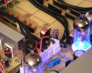
The TDA1541A output currents were transported to the I/V resistors (placed close to the input tube), using Van-Damme OFC studio patch cable.
Hi soundcheck,
Now you just need to get rid of your active output stage to become member of the stacked-1543-less-is-more fanclub.
Sometimes less is actually just less, then something needs to be added to get more.
I have very good reasons to add an active output stage:
- Differential to single-ended conversion, doubles the output voltage, halves the ac voltage at the DAC outputs, cancels common noise and provides lower THD.
- Low output impedance (less problems with connected loads).
- High-impedance load across the passive I/V resistor (minimizes non-linearity errors).
- Isolating load from passive I/V resistor.
- Ability to use low resistance values for passive I/V conversion > lower resistance value, lower noise.
I had difficulties to find anything else and better at the required values.
Is somebody selling these kind of resistors at reasonable prices?
Well this is diyAudio, why not make your own copper wire resistors like I did?
You need some thin lacquered copper wire, and a coil former. I used laquered copper wire from a relay with 230V coil voltage.
I posted it before, but here is how to make a NON-inductive copper wire resistor:
Calculate the total length you need (Ohms/meter + desired resistor value). Next cut the copper wire to calculated length, plus some extra for tolerances. Then fold the wire at the half of the length, carefully twist it together (hand drill), then carefully detach it from the hand drill and release the tension (otherwise the wires get curled-up, and you can start all over again). Then wind it on a coil former. Now shorten the wires to achieve exact resistor value. Finally solder the wires to the pins on the coil former.
The attached photograph shows a twin non-inductive copper wire resistor (2 x 39R). It's a twin mobius loop, wound on a standard coil former. It took 2 x 17 meters of thin copper wire to construct it. The center connection is common (GND).
The TDA1541A output currents were transported to the I/V resistors (placed close to the input tube), using Van-Damme OFC studio patch cable.
Attachments
Hi ecdesigns.
I hope you realized that I was joking about "stacked-1543-less-is-more fanclub". 😉
DIY: That's what I do all the time. Though, when it comes to start making resistors. Hmmmh. Perhaps that's too much. My time is kind of limited.
Ok,OK. I know. Instead of writing lenghtly posts I could rather build
a resistor. 😉 (BTW: 25 years back I learned how to build relays and bifilar windings). I have one problems with these kind of coils. They ususally pick up a lot of vibration energy if done wrongly. Causing fuzzy sound.
I found interesting non-inductive, wirewound, purest copper resistors at Mundorf. Called Mundorf M-resist supreme. It seems that the highest value is 33R. I'll check it out tomorrow if I can also get higher values.
Cheers
ECdesigns diy resistor is very good. (twisted copper wire and then winded on a piece of wood) Performs very well, accurate and very low induction i guess. Not a great deal of work. Made two for a preamp output resistor.
No more DI8?
EC, what do you mean DI8 DAC is no more???? I was going to buy the kit. Why replace this with a 4 chip version? I thought you were going to implement your new passive I/V + tube output stage on the DI8.
EC, what do you mean DI8 DAC is no more???? I was going to buy the kit. Why replace this with a 4 chip version? I thought you were going to implement your new passive I/V + tube output stage on the DI8.
Hi MGH,
I only noted that my DI8M REFERENCE DAC is no more. It has now been replaced by the DI4T.
Yes, at first I just added passive I/V and used tube-only output on the DI8M.
Then 4 x interpolation was tested with another DAC prototype, and showed consistent improved performance over NOS, 2 x, and 8 x interpolation. So that's why I switched to the 4 chip version.
Both DI8M and DI16 PCBs will remain available of course.
EC, what do you mean DI8 DAC is no more???? I was going to buy the kit. Why replace this with a 4 chip version? I thought you were going to implement your new passive I/V + tube output stage on the DI8.
I only noted that my DI8M REFERENCE DAC is no more. It has now been replaced by the DI4T.
Yes, at first I just added passive I/V and used tube-only output on the DI8M.
Then 4 x interpolation was tested with another DAC prototype, and showed consistent improved performance over NOS, 2 x, and 8 x interpolation. So that's why I switched to the 4 chip version.
Both DI8M and DI16 PCBs will remain available of course.
Hi folks.
I'd like to stress one issue (again).
I would like to slave the PC to the DAC, which would mean that I need to get away from USB.
John mentioned that he is using Toslink now. Assuming that the PC interface has WC-input it should be quite easy to build a DAC-master-clock with a WC-output. That might solve quite some issues on the PC side!!?!?
Any opinions about this? Did anybody try it? How would such a Master-Clock output would look like?
THX
- Home
- Source & Line
- Digital Line Level
- Building the ultimate NOS DAC using TDA1541A