Hi rtd,
The TDA1541A DEM clock oscillator produces similar clock signal amplitudes, 5VPP signals may prevent correct DEM clock injection, and increase switching noise levels. I would at least put a 22 ... 100 Ohms damping resistor in series with the DEM clock signal.
You need to double the reclocker master clock frequency from 48 to 96 MHz. This could be done with a clock doubler (few gates), or by using a Tent 67.7376 MHz low jitter clock (exact multiple).
Since both BCK and master clock frequency are now doubled, the LRM should function correctly. You have to divide BCK by 16 in order to get the 352.8 KHz DEM clock.
I implemented the DEM Clock. I understood that the attenuator (680/180) was here to give 1 Vrms pp. I tried to remove it and let only the 470 pF caps... This has effect on sound mainly louder bass and so more bodied sound. So the question was why 1 VRms should be used ?
The TDA1541A DEM clock oscillator produces similar clock signal amplitudes, 5VPP signals may prevent correct DEM clock injection, and increase switching noise levels. I would at least put a 22 ... 100 Ohms damping resistor in series with the DEM clock signal.
I know fit a DIR9001 and is planning to use the last LRM as described here too. With the SAA7220, i will have BCK à 5.6448 MHz which is not at least a multiple of 48 Mhz... To keep the same ratio (x17) will I have to use some 96 Mhz Xo ?
You need to double the reclocker master clock frequency from 48 to 96 MHz. This could be done with a clock doubler (few gates), or by using a Tent 67.7376 MHz low jitter clock (exact multiple).
Since both BCK and master clock frequency are now doubled, the LRM should function correctly. You have to divide BCK by 16 in order to get the 352.8 KHz DEM clock.
Hi audiodesign,
Ok I can stop the DI DAC project then 🙂
Nice to see somebody actually design and build a DAC, instead of only discussing about it, my compliments!
I see you have been tweaking the I/V resistor, it's a good sign If you can hear differences in sound quality between various I/V resistor types.
It's a straight-forward design, so you might add some improvements:
1) keep the CS8214 loop filter connections as short as possible and use small SMD components for 68nF and 470 Ohms. If you optimize the CS8414 SPDIF receiver, you could get jitter down to approx. 200ps, that should be fine for a NOS DAC (173ps RMS).
2) There will also be a small delay between L and R channels (11.34us), since no time correction is applied (you could try stopped-clock operation). There is an application note about this circuit.
3) You could install some damping resistors in BCK, L/R and DATA lines (22r ... 100R). This suppresses signal overshoot / ringing.
I have published now the my new DAC better than any TDA1541
Ok I can stop the DI DAC project then 🙂
Nice to see somebody actually design and build a DAC, instead of only discussing about it, my compliments!
I see you have been tweaking the I/V resistor, it's a good sign If you can hear differences in sound quality between various I/V resistor types.
It's a straight-forward design, so you might add some improvements:
1) keep the CS8214 loop filter connections as short as possible and use small SMD components for 68nF and 470 Ohms. If you optimize the CS8414 SPDIF receiver, you could get jitter down to approx. 200ps, that should be fine for a NOS DAC (173ps RMS).
2) There will also be a small delay between L and R channels (11.34us), since no time correction is applied (you could try stopped-clock operation). There is an application note about this circuit.
3) You could install some damping resistors in BCK, L/R and DATA lines (22r ... 100R). This suppresses signal overshoot / ringing.
The AD1865 is regarded good sounding indeed, no experience though.
Another comment about audio from PC. Unfortunately EAC, Exact Audio Copy is not available for Linux, but can be a very helpful program to rip your music from cd to hd, with no reading errors, jitter and interpolation roundings. EAC avoud all that problems and rip your CD in the best way. When EAC is used, and you still want to use the merits of Linux playback a dual boot win/linux system with a FAT32 audio partition on HD could be an option.
http://www.exactaudiocopy.de/
audiodesign said:I have published now the my new DAC better than any TDA1541
http://www.audiodesignguide.com/DacEnd/index.html
Hi Audiodesign,
Did you compare your dac with the DI8 from ecdesigns ?
Conform your schematic you did not impliment the MSB trim option
what is one of the nice things of the AD1865.
You did not do that on purpose ?
Onno
XP vs ubuntu on a laptop
Hi All,
Until now nobody gives a straigth answer if disabling both drivers under "Battery" in the device manager does improve XP sound.
Nobody is using a laptop ??
Onno
Hi All,
Until now nobody gives a straigth answer if disabling both drivers under "Battery" in the device manager does improve XP sound.
Nobody is using a laptop ??
Onno
Hi Audiodesign,
Your post was very impolite. Nevertheless, you receive kindness in return "on this thread"
Un po di gentilezza non fa male...
Kind regards,
M
Hi audiodesign,
quote:
I have published now the my new DAC better than any TDA1541
Ok I can stop the DI DAC project then
Nice to see somebody actually design and build a DAC, instead of only discussing about it, my compliments!
I see you have been tweaking the I/V resistor, it's a good sign If you can hear differences in sound quality between various I/V resistor types.
It's a straight-forward design, so you might add some improvements:
1) keep the CS8214 loop filter connections as short as possible and use small SMD components for 68nF and 470 Ohms. If you optimize the CS8414 SPDIF receiver, you could get jitter down to approx. 200ps, that should be fine for a NOS DAC (173ps RMS).
2) There will also be a small delay between L and R channels (11.34us), since no time correction is applied (you could try stopped-clock operation). There is an application note about this circuit.
3) You could install some damping resistors in BCK, L/R and DATA lines (22r ... 100R). This suppresses signal overshoot / ringing.
Your post was very impolite. Nevertheless, you receive kindness in return "on this thread"
Un po di gentilezza non fa male...
Kind regards,
M
stopped-clock operation
Hi audiodesign,
Left channel output is latched on negative going edge of WS, (LL), right channel output is latched on the inverted WS signal (LR) > 74HC04, on the moment that WS goes high. If the WS signal frequency equals 44.1 KHz, period time equals 1 / 44,100 = 22.6uS. The time delay between positive and negative going edge of WS then equals 22.68 / 2 = 11.34uS.
I attached a schematic for stopped-clock operation (Analog Devices application note)
Hi audiodesign,
Why 11.34us ?
Left channel output is latched on negative going edge of WS, (LL), right channel output is latched on the inverted WS signal (LR) > 74HC04, on the moment that WS goes high. If the WS signal frequency equals 44.1 KHz, period time equals 1 / 44,100 = 22.6uS. The time delay between positive and negative going edge of WS then equals 22.68 / 2 = 11.34uS.
I attached a schematic for stopped-clock operation (Analog Devices application note)
Attachments

Cdparanoia
Hi tubee,
For Ubuntu there is Cdparanoia:
http://xiph.org/paranoia/
http://directory.fsf.org/project/cdparanoia/
No need for dual boot with EAC.
Hi tubee,
Another comment about audio from PC. Unfortunately EAC, Exact Audio Copy is not available for Linux
EAC avoud all that problems and rip your CD in the best way
For Ubuntu there is Cdparanoia:
http://xiph.org/paranoia/
http://directory.fsf.org/project/cdparanoia/
No need for dual boot with EAC.
Hi folks.
Just sneaking in to your extremely long thread over here. 😉
-----------------------------------------------------------
PC as source - OFF TOPIC:
My 2 cents:
Linux is the most flexible and the only real "DIY" system . Period.
Though it's nothing for somebody who is not willing to dig into the depth of kernel configurations, driver manipulations and so forth.
A current off-the-shelve Ubuntu Studio is not better
then neither an OS-X nor Vista - it needs to be tweaked as any OS.
XXHighend (Vista) is quite a nice piece of Software. It sounds great.
In the end bit-transparency resp. bit-perfection can be achieved pretty much with any OS if the settings are correct.
Where it differs is the jitter induced to the signal.
Then you're back to the question of which DAC can cope best with the Jiitter. You're trying again to solve an issue which should have been avoided earlier!
Best solution?!?!:
Avoid that jitter by running a fully synched master-clocked system.
I know of systems which doesn't change at all, when applying these OS tweaks - if clocked with e.g. a Big Ben or similar and your soundcard is slaved to the Big Ben.
I am actually still looking for a nice brutefir filtererd multi-channel solution. PC and 3 DACs ( at such a quality you're discussing over here) - mastersynched - fireing my active speakers.
Anybody around here who implemented a mutichannel version of
the discussed DACs?
Notes:
1. You do not need ASIO or KS under Linux. You get right to the interface.
2. There is no better ripper than EAC or dbPoweramp.
CdParanoia sucks - very insecure. There is a new Linux ripper called Rubyripper which comes with more security features then cdparanoia -it's Ok but still it is not at the level of EAC & dbPA. Once you get used to the Accuraterip -feature (EAC and dbPA) you don't want to miss it any longer. If you run 24 or higher speed with perfect rip results you'll save a lot of time.
3. You also need to have a look at CICS PC optimisations posted on Audio Asylum which are quite impressive.
----------------------------------------------------
Cheers
With the comments of Soundcheck & Onnosr we are getting somewhere!
EAC is nice indeed, even for a linux hooligan as Soundcheck is.😀 😉
Onnosr, the LSB trim pot is very useful, i tried that on a PCM56, you can "turn away" or minimise the last little bit of distorsion in eg female voices.
EAC is nice indeed, even for a linux hooligan as Soundcheck is.😀 😉
Onnosr, the LSB trim pot is very useful, i tried that on a PCM56, you can "turn away" or minimise the last little bit of distorsion in eg female voices.
bit-perfect data easy?
Hi soundcheck,
Thanks for the tips,
Jitter is basically determined by DAC hardware (clock / reclock architecture). Achieving bit-perfection is actually the biggest problem.
Pre-vista:
Kmixer + GFX cannot be switched-off, not even for USB audio devices.
Trunctuation errors due to MMX CPU extensions.
Possibility of multiple sample rate conversions 44.1 > 48 > 44.1, with accompanied trunctuation errors.
Work-around (not a real solution). Kernel streaming / ASIO drivers.
ASIO drivers are from Steinberg, ASIO4ALL is possibly not ok, too many bugs / updates. Kernel streaming only with foobar.
iTunes for windows uses Quicktime and Kmixer + GFX, same problem, no bit perfect data.
Quote:
Kmixer resamples to 48 KHz IIRC, hence the "bit-perfectness" goes out of the window. Also, it may do volume adjustment. Digital volume adjustment = loss of precision. Whether any of the 2, or even both combined, will produce an audible effect is up to you to decide.
Bypassing the KMIXER via Kernel Streaming, ASIO or custom driver will in it self make the data to the dac bit perfect. The KMIXER will not be magically bypassed simply by plugging in a dac is silly or as an engineer at Microsoft said yesterday:
Quote:
There is a huge thread around the Benchmark DAC1-USB on head-fi that claimed it had some magic USB implementation that bypassed kmixer without resorting to kernel streaming.
I was not sure whether it was lack of understanding or over-aggressive marketing but I am afraid any device using the standard USB audio driver will have to live with kmixer.
Explanation Microsoft:
==============
Some of the design goals for the KMixer that affects this issue are:
1) Create a standard interface to the audio device
2) Handle multiple asynchronous streams of audio
3) Handle streams of different sampling rates
4) Efficient, low CPU usage (keep data streams moving, even on slower systems)
5) Volume control
In order to meet these goals, the KMixer can not guarantee bit perfect playback. Hence it does not support non-PCM streams. The DTS CD (masquerading as a PCM stream) is corrupted in the process. DVD and CD players don't need to meet the above requirements, so they simply pass the stream along. DTS really should have standardized their format. Regardless, the bit manipulation occurs because of volume control.
Since most PCM data is 16 bits, on MMX systems the KMixer uses 16 bit math to take advantage of the SIMD parallelism of MMX. 15 bits are used for multiplication and 1 bit for sign. This means that the KMixer can not represent an amplitude of 1.0. The best it can do is 7FFF/8000. So on MMX systems, when the volume is set to 0dB attenuation, KMixer still attenuates the signal slightly - so the bits are changed.
On non-MMX systems, the KMixer uses floating point math to handle volume. This results in higher CPU usage, but allows the KMixer to reach an amplitude of 1.0. The floating point numbers are then converted back to integers (because that's what the sound card is connected with) and ends up dithering the stream in the process.
>>>> When bit perfect playback is necessary, Kernel Streaming is recommended. <<<<
Vista:
Yet another software layer added, now it's possible for each application to tamper with audio data.
So data can now be tampered with in:
1: application
2: mixer for each application
3: global mixer
Still no bit-perfect playback. Perhaps XXHighend with engine #3 will solve this little problem.
Ubuntu / Linux:
Probably requires tweaking and the use of the correct drivers for your PC hardware. However it should be possible to achieve bit-perfect playback.
All I can personally advise, is to use the DI DACs in combination with mac OSX (USB or SPDIF/TOSLINK). Mac OSX provides bit-perfect playback without tweaking.
Oh, yes I almost forgot, jitter!
Well I solved that some time ago:
1) UTOS2 digital receiver, supports both USB and SPDIF/TOSLINK. It provides full galvanic insulation between source and DAC (High-Speed opto-couplers). This prevents ground-loop problems and computer induced noise is blocked.
2) LRM local reclocker module, uses an ultra low jitter masterclock to reclock the timing signal. The reclocker is placed directly on the DI DAC mainboard, and clock distribution is highly tuned to maintain ultra low masterclock jitter. It has a large capture range and blocks input jitter (including jitter introduced by the opto-couplers) up to a few thousand picoseconds.
The name CDparanoia perfectly describes the problem, blowing up insignificant details out of proportion. In practice, almost every CD ripper will do fine.
Hi soundcheck,
Thanks for the tips,
In the end bit-transparency resp. bit-perfection can be achieved pretty much with any OS if the settings are correct.
Jitter is basically determined by DAC hardware (clock / reclock architecture). Achieving bit-perfection is actually the biggest problem.
Pre-vista:
Kmixer + GFX cannot be switched-off, not even for USB audio devices.
Trunctuation errors due to MMX CPU extensions.
Possibility of multiple sample rate conversions 44.1 > 48 > 44.1, with accompanied trunctuation errors.
Work-around (not a real solution). Kernel streaming / ASIO drivers.
ASIO drivers are from Steinberg, ASIO4ALL is possibly not ok, too many bugs / updates. Kernel streaming only with foobar.
iTunes for windows uses Quicktime and Kmixer + GFX, same problem, no bit perfect data.
Quote:
Kmixer resamples to 48 KHz IIRC, hence the "bit-perfectness" goes out of the window. Also, it may do volume adjustment. Digital volume adjustment = loss of precision. Whether any of the 2, or even both combined, will produce an audible effect is up to you to decide.
Bypassing the KMIXER via Kernel Streaming, ASIO or custom driver will in it self make the data to the dac bit perfect. The KMIXER will not be magically bypassed simply by plugging in a dac is silly or as an engineer at Microsoft said yesterday:
Quote:
There is a huge thread around the Benchmark DAC1-USB on head-fi that claimed it had some magic USB implementation that bypassed kmixer without resorting to kernel streaming.
I was not sure whether it was lack of understanding or over-aggressive marketing but I am afraid any device using the standard USB audio driver will have to live with kmixer.
Explanation Microsoft:
==============
Some of the design goals for the KMixer that affects this issue are:
1) Create a standard interface to the audio device
2) Handle multiple asynchronous streams of audio
3) Handle streams of different sampling rates
4) Efficient, low CPU usage (keep data streams moving, even on slower systems)
5) Volume control
In order to meet these goals, the KMixer can not guarantee bit perfect playback. Hence it does not support non-PCM streams. The DTS CD (masquerading as a PCM stream) is corrupted in the process. DVD and CD players don't need to meet the above requirements, so they simply pass the stream along. DTS really should have standardized their format. Regardless, the bit manipulation occurs because of volume control.
Since most PCM data is 16 bits, on MMX systems the KMixer uses 16 bit math to take advantage of the SIMD parallelism of MMX. 15 bits are used for multiplication and 1 bit for sign. This means that the KMixer can not represent an amplitude of 1.0. The best it can do is 7FFF/8000. So on MMX systems, when the volume is set to 0dB attenuation, KMixer still attenuates the signal slightly - so the bits are changed.
On non-MMX systems, the KMixer uses floating point math to handle volume. This results in higher CPU usage, but allows the KMixer to reach an amplitude of 1.0. The floating point numbers are then converted back to integers (because that's what the sound card is connected with) and ends up dithering the stream in the process.
>>>> When bit perfect playback is necessary, Kernel Streaming is recommended. <<<<
Vista:
Yet another software layer added, now it's possible for each application to tamper with audio data.
So data can now be tampered with in:
1: application
2: mixer for each application
3: global mixer
Still no bit-perfect playback. Perhaps XXHighend with engine #3 will solve this little problem.
Ubuntu / Linux:
Probably requires tweaking and the use of the correct drivers for your PC hardware. However it should be possible to achieve bit-perfect playback.
All I can personally advise, is to use the DI DACs in combination with mac OSX (USB or SPDIF/TOSLINK). Mac OSX provides bit-perfect playback without tweaking.
Where it differs is the jitter induced to the signal.
Oh, yes I almost forgot, jitter!
Well I solved that some time ago:
1) UTOS2 digital receiver, supports both USB and SPDIF/TOSLINK. It provides full galvanic insulation between source and DAC (High-Speed opto-couplers). This prevents ground-loop problems and computer induced noise is blocked.
2) LRM local reclocker module, uses an ultra low jitter masterclock to reclock the timing signal. The reclocker is placed directly on the DI DAC mainboard, and clock distribution is highly tuned to maintain ultra low masterclock jitter. It has a large capture range and blocks input jitter (including jitter introduced by the opto-couplers) up to a few thousand picoseconds.
CdParanoia sucks - very insecure. There is a new Linux ripper called Rubyripper which comes with more security features then cdparanoia
The name CDparanoia perfectly describes the problem, blowing up insignificant details out of proportion. In practice, almost every CD ripper will do fine.
-ecdesigns-:
I have two questions about the DI-16 PCB I am stuffing:
for R13-R16, I have seen several values, one on the pdf stuffing guide, one value on the BOM you provided, and another value on the schematic you provided. I purchased and installed the 0.1% 1K and 2K21 values. Is this sufficient?
for the 5 regulator ICs, how much heat sinking is sufficient?
Hi luvdunhill,
R13 ... R16 are used for output attenuator. Depending on desired output voltage (1Vrms or 2Vrms), the values are different:
1V rms (standard) R13, R14 = 2K (2K21), R15, R16 = 500 Ohm (510 Ohm).
2V rms (I use this value for my set) R13, R14 = 2K (2K21), R15, R16 = 1K Ohm.
These values are dimensioned to add the TUBEDIFF stage, that's why the resistor values are relatively high (tubediff output impedance).
When not using the TUBEDIFF modules, output impedance can be lowered, by decreasing resistor values for R13 ... R16. The lowest usable values depend on LM4562 specifications.
1V rms (standard) R13, R14 = 470 Ohm, R15, R16 = 120 Ohm.
2V rms (I use this value for my set) R13, R14 = 470 Ohm, R15, R16 = 220 Ohm.
I already posted an example of calculating output attenuator resistor values.
It's best to mount them directly to an aluminum housing, or use a construction where the heatsink is thermally connected to a metal housing. Both U36 and U37 need sufficient cooling. Each TDA1543 group consumes 0.25 * 8 = 2W typical, current will be I = P / V = 2 / 6 = 333mA. When applying approx. 10V to the 7806 regulators, typical power dissipation in each regulator will be P = V * I = (10 - 6) * 0.333 = 1.33W.
for R13-R16, I have seen several values, one on the pdf stuffing guide, one value on the BOM you provided, and another value on the schematic you provided. I purchased and installed the 0.1% 1K and 2K21 values. Is this sufficient?
R13 ... R16 are used for output attenuator. Depending on desired output voltage (1Vrms or 2Vrms), the values are different:
1V rms (standard) R13, R14 = 2K (2K21), R15, R16 = 500 Ohm (510 Ohm).
2V rms (I use this value for my set) R13, R14 = 2K (2K21), R15, R16 = 1K Ohm.
These values are dimensioned to add the TUBEDIFF stage, that's why the resistor values are relatively high (tubediff output impedance).
When not using the TUBEDIFF modules, output impedance can be lowered, by decreasing resistor values for R13 ... R16. The lowest usable values depend on LM4562 specifications.
1V rms (standard) R13, R14 = 470 Ohm, R15, R16 = 120 Ohm.
2V rms (I use this value for my set) R13, R14 = 470 Ohm, R15, R16 = 220 Ohm.
I already posted an example of calculating output attenuator resistor values.
for the 5 regulator ICs, how much heat sinking is sufficient?
It's best to mount them directly to an aluminum housing, or use a construction where the heatsink is thermally connected to a metal housing. Both U36 and U37 need sufficient cooling. Each TDA1543 group consumes 0.25 * 8 = 2W typical, current will be I = P / V = 2 / 6 = 333mA. When applying approx. 10V to the 7806 regulators, typical power dissipation in each regulator will be P = V * I = (10 - 6) * 0.333 = 1.33W.
Hi -ecdesigns- 🙂
Talking about Vregs, I swapped the 7806 days ago for "TeddyRegs":
http://www.pinkfishmedia.net/forum/showthread.php?t=39990
It uses tantalum caps and small (0805) X7R ceramic caps. I use BC550 instead of JFet, for the Darlington.
I will replace the 7X15 regs, but I ran out of chips.
They are so much better than standard Vregs in every aspect that I am putting them everywhere, safe on clocks, because they take few seconds to settle.
Briefly: bass goes deeper and the harmonic bass content is better delineated; midrange is so soft and elegant; highs are sweeter. Overall, the flow of music is more natural.
Do you think D44H11 is fast enough?
GBP is 50MHz; switching delay and rise times: 300ns; storage time: 500ns; fall time: 150 ns.
With this mod and with your Noise gain manipulation tip the DAC is making sweet music.
About resistors, you were right again: the lower noise R (that you include in your kits) improve detail and clarity evidently.
One question:
On my DI8X4 I used 18K as Rref for TDA1543 . Can I use this value for DI16?
Regards,
M
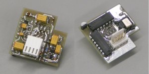
LRM2 / 96 MHz local reclocker
Hi maxlorenz,
The "TeddyRegs" consist of a plain adjustable voltage regulator, followed by a gyrator. It's basically the same technique used in the TUBEDIFF module. I placed gyrators in the anode of each triode, the result is effective suppression of hum and interference.
Both LT1086 and LM137 produce typical 150uV @5V and 450uV @15V. The "bad" 78XX produces only typical 42uV @5V and 90uV @ 15V. So perhaps it's better to select a 78XX regulator with slightly higher output voltage (7808), and then add the gyrator.
Clocks and reclockers would benefit from a stable low-noise power supply too. But you need a very stable voltage with very low dynamic impedance right at the crystal oscillator power supply pins. Even a few inches of wire can pick-up interference and mess-up the oscillator power supply again.
I currently use band-gap shunt regulators (LM336-5.0), programmed at 3.85V, large capacitance tantalium caps (470uF / 6V), and multiple COG 100nF decoupling caps. The shunt regulator series resistor is part of the power supply LC filter, the shunt regulator keeps the voltage close to the chip power supply pins extremely constant.
I now use them for masterclock, clock doubler, reclocker & clock buffers. I added a photograph of the LRM2, it's a new 96MHz shiftregister reclocker with clock doubler. I placed the LM336-5.0 bandgap reference diodes (TO-92) very close to both reclocker and masterclock oscillator. I used damping resistors on all clock signal lines, these resistors were tuned for lowest jitter / fastest clock signal transients.
The LRM2 seems to work very effectively, it's virtually impossible to hear any difference in sound quality between TOSLINK, coax/BNC or USB. I use it together with the UTOS2 module that also blocks digital audio source noise. The LRM2 increases micro-detail, and provides better transparency and focus.
But power supply (noise) this isn't the only problem causing clock jitter. Optimized clock distribution is also very important. There is a lot that can go wrong with clock distribution, and the result is a significant increase in clock jitter at the DAC timing input, regardless of the ultra-low jitter masterclock.
You don't need a fast switching transistor for a gyrator, but I guess this transistor would be ok. It's also possible to use power darlingtons.
Yes, I use noise-gain manipulation in the DI8M too, I now use 120 K Ohm for differential stage (2K5 bulk metal foil feedback resistor), and 12 K Ohm for the I/V stages (237 Ohm Arcol 0.1% feedback resistor). The effect is better focussed, cleaner, more analogue sound.
At first I thought 1% metal film were OK for audio, these have low noise and relative high accuracy, so why bother with expensive low noise / low TC resistors. Unfortunately low TC (high-priced) resistors do improve detail and clarity, simply because they produce lower noise than plain 1% metal film resistors. Other possibility to lower noise is to use relatively low resistor values, and resistors with higher power rating.
I now use the following resistors in the DI8M:
- Vishay 0.01% bulk metal foil
- Arcol / Tyco 0.1% metal film
- Beyschlag 1% / 1W metal film
Yes you can use them.
Hi maxlorenz,
Talking about Vregs, I swapped the 7806 days ago for "TeddyRegs":
The "TeddyRegs" consist of a plain adjustable voltage regulator, followed by a gyrator. It's basically the same technique used in the TUBEDIFF module. I placed gyrators in the anode of each triode, the result is effective suppression of hum and interference.
Both LT1086 and LM137 produce typical 150uV @5V and 450uV @15V. The "bad" 78XX produces only typical 42uV @5V and 90uV @ 15V. So perhaps it's better to select a 78XX regulator with slightly higher output voltage (7808), and then add the gyrator.
safe on clocks, because they take few seconds to settle.
Clocks and reclockers would benefit from a stable low-noise power supply too. But you need a very stable voltage with very low dynamic impedance right at the crystal oscillator power supply pins. Even a few inches of wire can pick-up interference and mess-up the oscillator power supply again.
I currently use band-gap shunt regulators (LM336-5.0), programmed at 3.85V, large capacitance tantalium caps (470uF / 6V), and multiple COG 100nF decoupling caps. The shunt regulator series resistor is part of the power supply LC filter, the shunt regulator keeps the voltage close to the chip power supply pins extremely constant.
I now use them for masterclock, clock doubler, reclocker & clock buffers. I added a photograph of the LRM2, it's a new 96MHz shiftregister reclocker with clock doubler. I placed the LM336-5.0 bandgap reference diodes (TO-92) very close to both reclocker and masterclock oscillator. I used damping resistors on all clock signal lines, these resistors were tuned for lowest jitter / fastest clock signal transients.
The LRM2 seems to work very effectively, it's virtually impossible to hear any difference in sound quality between TOSLINK, coax/BNC or USB. I use it together with the UTOS2 module that also blocks digital audio source noise. The LRM2 increases micro-detail, and provides better transparency and focus.
But power supply (noise) this isn't the only problem causing clock jitter. Optimized clock distribution is also very important. There is a lot that can go wrong with clock distribution, and the result is a significant increase in clock jitter at the DAC timing input, regardless of the ultra-low jitter masterclock.
Do you think D44H11 is fast enough?
GBP is 50MHz; switching delay and rise times: 300ns; storage time: 500ns; fall time: 150 ns.
You don't need a fast switching transistor for a gyrator, but I guess this transistor would be ok. It's also possible to use power darlingtons.
With this mod and with your Noise gain manipulation tip the DAC is making sweet music.
Yes, I use noise-gain manipulation in the DI8M too, I now use 120 K Ohm for differential stage (2K5 bulk metal foil feedback resistor), and 12 K Ohm for the I/V stages (237 Ohm Arcol 0.1% feedback resistor). The effect is better focussed, cleaner, more analogue sound.
About resistors, you were right again: the lower noise R (that you include in your kits) improve detail and clarity evidently.
At first I thought 1% metal film were OK for audio, these have low noise and relative high accuracy, so why bother with expensive low noise / low TC resistors. Unfortunately low TC (high-priced) resistors do improve detail and clarity, simply because they produce lower noise than plain 1% metal film resistors. Other possibility to lower noise is to use relatively low resistor values, and resistors with higher power rating.
I now use the following resistors in the DI8M:
- Vishay 0.01% bulk metal foil
- Arcol / Tyco 0.1% metal film
- Beyschlag 1% / 1W metal film
One question:
On my DI8X4 I used 18K as Rref for TDA1543 . Can I use this value for DI16?
Yes you can use them.
Attachments
Re: LRM2 / 96 MHz local reclocker
once the UTOS modules are available to purchase, I'd like to buy one!
-ecdesigns- said:[I use it together with the UTOS2 module that also blocks digital audio source noise.
once the UTOS modules are available to purchase, I'd like to buy one!
DI8M block diagram
Hi all,
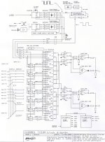
I get a lot of questions through email about DI DAC operation. So I made a block diagram that shows how all major DI8M circuits are interconnected.
At the top is the UTOS2 digital audio receiver. It has a PCM2706 in bus powered mode that's connected to the DAC through high-speed opto-couplers. This blocks source noise and prevents ground loops. The PCM2706 runs on a separate 12 MHz crystal oscillator.
The CS8416 SPDIF receiver has galvanic insulation at both input (TOSLINK & coax / BNC), and output (high-speed opto-couplers). The unused interface is shut-down completely, either by computer power-down, pulling USB plug or by the SPDIF power supply switcher. Only the receiver that's operational, passes the I2S data (opto-couplers are open collector type). The receiver status LED indicates what interface is selected, and if the CS8416 is locked.
The timing signal (BCK) is reclocked in the shiftregister reclocker (LRM2), running at 96 MHz. The LRM2 blocks phase noise up to a few thousand pico-seconds. So digital audio source jitter is now irrelevant, and no longer affects sound quality. Jitter is now determined by the LRM2 only. This means that it's sufficient to provide bit-perfect data only.
Next The I2S signals enter I2S buffers (on the timing module). BCK drives the DEM clock divider to derive 352.8 KHz @ 2.8224 MHz BCK rate. Note that DAC1 gets non-inverted BCK, since both DATA and WS don't change on the negative going edge of BCK. DAC2 ... 8 get both WS and DATA from the delay circuit, since these delay circuits latch at the positive going edge of BCK, the DAC chips need to be triggered at the negative going edge of BCK (when both delayed DATA and WS are stable). That's why they get the inverted BCK signal.
The DAC chips receive (and latch their outputs) after 8BCK delays, so the sample will appear sequentially as illustrated in the timing diagram. In other words, the sample rate is multiplied by 8, giving 352.8 KHz sample rate (interpolated samples).
There are also two DAC groups, each containing 4 DAC chips, one group receives non-inverted data, the other inverted data. Note that each group outputs a partly interpolated signal. The combined full-scale current of each DAC group equals 16mA. Depending on DAC bit accuracy, bit resolution could be doubled by each doubling of the DAC chips, theoretically providing max. 19 bit resolution. This resolution is obtained by adding 8 * 16 bit full scale currents (4mA), then dividing them at the DAC output to obtain 2V RMS signal. Now if only one DAC chip would be operational, max. output voltage would be 2 / 8 = 250mV, but it would already have 16 bit resolution.
As more DAC chips add their output current, both output voltage and bit resolution will increase accordingly. Since DAC currents are added together, this process should provide monotocity within each DAC group. Errors could be introduced by tolerances in DAC full scale current, IV and diff amp stages. These errors can be minimized by tuning.
Each DAC group drives an OP-amp I/V converter (LM4562). In order to eliminate most of the typical OP-amp I/V "issues", the OP-amp outputs were isolated from capacitive loads, low noise components were used in the feedback loop, output was pulled into class A, and noise-gain manipulation was applied. Now we have 4 I/V outputs: IV(L), NIV(L), IV(R), and NIV(R). These I/V outputs contain DC offset voltages.
The diff amp completes interpolation by adding both IV and NIV signals, doubling the signal amplitude, cancelling DC offset and common interference. The output signal of this "semiconductor" diff amp is routed to a resistive output attenuator. Both IV and NIV outputs are also connected to a tube diff amp, it does basically the same as the semiconductor diff amp, but has no thermal memory distortion. This output is also routed to the resistive output attenuator, and added to the semiconductor diff amp signal. Both diff amps create a fairly neutral harmonics pattern that results in a transparent sound. So the tubediff amp is NOT added for the typical "tube" sound.
At the bottom of the diagram there is the DI8 power supply, it has a an integrated two-stage mains filter and can be set to both 115 or 230V operation. It feeds both the DI8 core, part of the UTOS2 module, and the LRM2. It also drives the tube status LEDs, these indicate when the tubes are operational. The DI8 power supply can be switched on / off by a 5V signal. The DI8M power supply also routes the mains voltage to the TUBEPS module.
The TUBEPS module provides the pre-stabilized 220V anode voltage, -12.6V filament supply (filaments in series), and -40V for the current sources. The filament current is limited, and slowly increases depending on filament temperature. If the filament voltage reaches a specified threshold, a FET supplies full power to the now pre-heated filaments. Next HV is switched-on, now the tube circuit smoothly settles to operating conditions.
Hi all,
I get a lot of questions through email about DI DAC operation. So I made a block diagram that shows how all major DI8M circuits are interconnected.
At the top is the UTOS2 digital audio receiver. It has a PCM2706 in bus powered mode that's connected to the DAC through high-speed opto-couplers. This blocks source noise and prevents ground loops. The PCM2706 runs on a separate 12 MHz crystal oscillator.
The CS8416 SPDIF receiver has galvanic insulation at both input (TOSLINK & coax / BNC), and output (high-speed opto-couplers). The unused interface is shut-down completely, either by computer power-down, pulling USB plug or by the SPDIF power supply switcher. Only the receiver that's operational, passes the I2S data (opto-couplers are open collector type). The receiver status LED indicates what interface is selected, and if the CS8416 is locked.
The timing signal (BCK) is reclocked in the shiftregister reclocker (LRM2), running at 96 MHz. The LRM2 blocks phase noise up to a few thousand pico-seconds. So digital audio source jitter is now irrelevant, and no longer affects sound quality. Jitter is now determined by the LRM2 only. This means that it's sufficient to provide bit-perfect data only.
Next The I2S signals enter I2S buffers (on the timing module). BCK drives the DEM clock divider to derive 352.8 KHz @ 2.8224 MHz BCK rate. Note that DAC1 gets non-inverted BCK, since both DATA and WS don't change on the negative going edge of BCK. DAC2 ... 8 get both WS and DATA from the delay circuit, since these delay circuits latch at the positive going edge of BCK, the DAC chips need to be triggered at the negative going edge of BCK (when both delayed DATA and WS are stable). That's why they get the inverted BCK signal.
The DAC chips receive (and latch their outputs) after 8BCK delays, so the sample will appear sequentially as illustrated in the timing diagram. In other words, the sample rate is multiplied by 8, giving 352.8 KHz sample rate (interpolated samples).
There are also two DAC groups, each containing 4 DAC chips, one group receives non-inverted data, the other inverted data. Note that each group outputs a partly interpolated signal. The combined full-scale current of each DAC group equals 16mA. Depending on DAC bit accuracy, bit resolution could be doubled by each doubling of the DAC chips, theoretically providing max. 19 bit resolution. This resolution is obtained by adding 8 * 16 bit full scale currents (4mA), then dividing them at the DAC output to obtain 2V RMS signal. Now if only one DAC chip would be operational, max. output voltage would be 2 / 8 = 250mV, but it would already have 16 bit resolution.
As more DAC chips add their output current, both output voltage and bit resolution will increase accordingly. Since DAC currents are added together, this process should provide monotocity within each DAC group. Errors could be introduced by tolerances in DAC full scale current, IV and diff amp stages. These errors can be minimized by tuning.
Each DAC group drives an OP-amp I/V converter (LM4562). In order to eliminate most of the typical OP-amp I/V "issues", the OP-amp outputs were isolated from capacitive loads, low noise components were used in the feedback loop, output was pulled into class A, and noise-gain manipulation was applied. Now we have 4 I/V outputs: IV(L), NIV(L), IV(R), and NIV(R). These I/V outputs contain DC offset voltages.
The diff amp completes interpolation by adding both IV and NIV signals, doubling the signal amplitude, cancelling DC offset and common interference. The output signal of this "semiconductor" diff amp is routed to a resistive output attenuator. Both IV and NIV outputs are also connected to a tube diff amp, it does basically the same as the semiconductor diff amp, but has no thermal memory distortion. This output is also routed to the resistive output attenuator, and added to the semiconductor diff amp signal. Both diff amps create a fairly neutral harmonics pattern that results in a transparent sound. So the tubediff amp is NOT added for the typical "tube" sound.
At the bottom of the diagram there is the DI8 power supply, it has a an integrated two-stage mains filter and can be set to both 115 or 230V operation. It feeds both the DI8 core, part of the UTOS2 module, and the LRM2. It also drives the tube status LEDs, these indicate when the tubes are operational. The DI8 power supply can be switched on / off by a 5V signal. The DI8M power supply also routes the mains voltage to the TUBEPS module.
The TUBEPS module provides the pre-stabilized 220V anode voltage, -12.6V filament supply (filaments in series), and -40V for the current sources. The filament current is limited, and slowly increases depending on filament temperature. If the filament voltage reaches a specified threshold, a FET supplies full power to the now pre-heated filaments. Next HV is switched-on, now the tube circuit smoothly settles to operating conditions.
Attachments
Hi -ecdesigns-. Thank you for your excellent reply (post #1876).
Please don't get me wrong with the Vregs swap; the sound was already very good but you know how this is...one seeks perfection AND knowledge/experience acquisition 🙂 I found it sounds better with TeddyRegs (safe the highs which might be a little too soft now)
Good tip about swapping LM317 for 7808: Vout shall be 6.4V, but can be tuned if I found the right resistors.
I know shunts are very good and I have some LM336 here to practice with 😉
It is very appealing and I shall try it when funds allow 😎
I see the enormous amount of work and brain involved in your restless search for the perfect digital source. You know you face big reject for example from people that think that computer based music can't reach HiEnd level. I think you are in better position than most (maybe than anyone) to reach the highest level.
So, no more DI2S? I could use some spare prototype, he, he
I have used power Darlington (BDX33C or something...) and the BC550+D44HX combination sounds better. It is said that every transistor sounds different in this unit. I have used BC550+BC550 Darlington in low current circuits and it also sounds good.
It is one of those tweaks that one can't believe it is not better known, so simple and effective...😕
So, you are using around 50*Rf now? Good, I can experiment with higher values too.
Arcol are good.
Gratefully yours,
M
Please don't get me wrong with the Vregs swap; the sound was already very good but you know how this is...one seeks perfection AND knowledge/experience acquisition 🙂 I found it sounds better with TeddyRegs (safe the highs which might be a little too soft now)
Good tip about swapping LM317 for 7808: Vout shall be 6.4V, but can be tuned if I found the right resistors.
I currently use band-gap shunt regulators (LM336-5.0), programmed at 3.85V, large capacitance tantalium caps (470uF / 6V), and multiple COG 100nF decoupling caps.
I know shunts are very good and I have some LM336 here to practice with 😉
I added a photograph of the LRM2, it's a new 96MHz shiftregister reclocker with clock doubler.
It is very appealing and I shall try it when funds allow 😎
I see the enormous amount of work and brain involved in your restless search for the perfect digital source. You know you face big reject for example from people that think that computer based music can't reach HiEnd level. I think you are in better position than most (maybe than anyone) to reach the highest level.
So, no more DI2S? I could use some spare prototype, he, he
You don't need a fast switching transistor for a gyrator, but I guess this transistor would be ok. It's also possible to use power darlingtons.
I have used power Darlington (BDX33C or something...) and the BC550+D44HX combination sounds better. It is said that every transistor sounds different in this unit. I have used BC550+BC550 Darlington in low current circuits and it also sounds good.
Yes, I use noise-gain manipulation in the DI8M too, I now use 120 K Ohm for differential stage (2K5 bulk metal foil feedback resistor), and 12 K Ohm for the I/V stages (237 Ohm Arcol 0.1% feedback resistor). The effect is better focussed, cleaner, more analogue sound.
It is one of those tweaks that one can't believe it is not better known, so simple and effective...😕
So, you are using around 50*Rf now? Good, I can experiment with higher values too.
Arcol are good.
Gratefully yours,
M
Re: bit-perfect data easy?
Might it be of use : 100% guaranteed ! 🙂
-ecdesigns- said:Vista:
Yet another software layer added, now it's possible for each application to tamper with audio data.
So data can now be tampered with in:
1: application
2: mixer for each application
3: global mixer
Still no bit-perfect playback. Perhaps XXHighend with engine #3 will solve this little problem.
Might it be of use : 100% guaranteed ! 🙂
- Home
- Source & Line
- Digital Line Level
- Building the ultimate NOS DAC using TDA1541A