Hello,
I've build the I2s to simultaneous converter(V1) on a CPLD from this theme:
https://www.diyaudio.com/community/threads/diy-i2s-to-simultaneous-converter-pcb.326972/
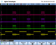
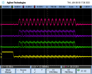
While I'm waiting for my TDA1541A PCB's to arrive I took some plots of the signals. Input is I2S 16bit, 192kHz. What puzzles me is that BCK is 12.3MHz which is high.
Please ignore the signal integrity "beauty" caused by the cable mess. 😆
I've build the I2s to simultaneous converter(V1) on a CPLD from this theme:
https://www.diyaudio.com/community/threads/diy-i2s-to-simultaneous-converter-pcb.326972/
While I'm waiting for my TDA1541A PCB's to arrive I took some plots of the signals. Input is I2S 16bit, 192kHz. What puzzles me is that BCK is 12.3MHz which is high.
Please ignore the signal integrity "beauty" caused by the cable mess. 😆
Attachments
OK. Interesting article, thanks.Пожалуйста, разместите сообщение на английском языке.
Yes.Особенно утечки на конденсаторах dem и возврат невыбранных битовых токов к + 5в.
Do you know who is behind Mvaudiolabs ?Here's another recent take on the "ultimate TDA1541":
https://www.mvaudiolabs.com/digital/tda1541a-reference-dac/
.
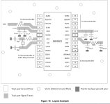
So , here are the sketches modified , I merge together the spdif board and the logic board , after all it seems logical 😎
I gave almost every traces more width , and reroute some off them too
not shown here but there is copper pour on both bottom board
still every thought welcome , I may have miss something or have made mistake 😉
.


I gave almost every traces more width , and reroute some off them too
not shown here but there is copper pour on both bottom board
still every thought welcome , I may have miss something or have made mistake 😉
.
Check lp5907 datasheet for layout considerations (decoupling caps must be verry close to ldo). Also lt3894/3045, i assume you use ldo’s on pcb , check “dac decouplings thread”, peufeu makes some nice considerations about those 3 pin ldo.
got it , I have made some adjustment 🙂
regarding the LDOVR regs , I use them somewhere else with good measurement so far , as far as they are "near" ( say few inchs ) from what they feed , I will have a look at the thread you mentioned
.

regarding the LDOVR regs , I use them somewhere else with good measurement so far , as far as they are "near" ( say few inchs ) from what they feed , I will have a look at the thread you mentioned
.
It is not easy to make your own DAC from scratch. Special attention should be paid to decoupling and power sources (regulators) because the same rules apply here as in RF electronics, interference is usually in the MHz range and it is difficult to get rid of them.
On the PCB with TDA1541, there is no decoupling at all on the TDA1541 power supply pins, and OS-CON and COG SMD fit perfectly there. OS-CON precisely because it is good at high frequencies.
On the PCB with TDA1541, there is no decoupling at all on the TDA1541 power supply pins, and OS-CON and COG SMD fit perfectly there. OS-CON precisely because it is good at high frequencies.
Here they are , I thought i could place them aftermath , but what's done is done , the value will depends on measurements .
here is the bottom side
I dont really start from scratch , much of the job has all ready be done on this thread 🙂
.

.
here is the bottom side
I dont really start from scratch , much of the job has all ready be done on this thread 🙂
.
.
Last edited:
Well, since interest seems a bit renewed, I have implemented twice now (3 if you count the non SM) a signed magnitude board, on 4 layers, refining the layout and using John's nuggets of gold he left all around the thread, all in all taking probably close to 100hrs. There were some issues with the logic on the first version, then xaled and I teamed up a bit. He sent me a care package with his own implementation of the signed magnitude logic to debug, but it didn't work, and i reimplemented my own once again, and it "almost" works, but something is still off and plays the music but gives a terrible hissing distorted sound, which i am sure is still from logic side and not analog issue, because it's nature changes based on sample rate and I2S format but i could not land on anything that works.
If anyone wants an (unassembled but BOM provided) board to test and play around with, im sending free of charge, just pay shipping. Who knows, maybe it just doesnt work for me and someone else can push it over the crest, or double check I2S timing with logic analyzer, someone more experienced with logic design. Actually if there is such a serious poster who wants to troubleshoot it and has their own 2x TDA1541A's I might send my own assembled board if you want. Im using non-A version but logic was designed with A version in mind, from everything i know and datasheet too it shouldn't make a difference but Philips did release a new digital filter to go with the A, i dont know if they changed anything about how it handles the input just enough to throw this off.
If anyone wants an (unassembled but BOM provided) board to test and play around with, im sending free of charge, just pay shipping. Who knows, maybe it just doesnt work for me and someone else can push it over the crest, or double check I2S timing with logic analyzer, someone more experienced with logic design. Actually if there is such a serious poster who wants to troubleshoot it and has their own 2x TDA1541A's I might send my own assembled board if you want. Im using non-A version but logic was designed with A version in mind, from everything i know and datasheet too it shouldn't make a difference but Philips did release a new digital filter to go with the A, i dont know if they changed anything about how it handles the input just enough to throw this off.
100u caps not installed because i have the non-A version, cant use 50hz DEM.

One is flipped upside down, because it significantly improves the layout, and makes it more elegant.


Signed magnitude logic based on post 7092

One is flipped upside down, because it significantly improves the layout, and makes it more elegant.
Signed magnitude logic based on post 7092
Last edited:

Did you solder 470pF between pins 16 and 17? I have a TDA1541 but a slightly younger HSH8714 which does not work without that capacitor which is not present in the DS of the TDA1541.
I have (underneath the board), but yes you are right I can confirm it does do some crunchy mess without it. That's a good tip because it says N.C on the datasheet for the non-A, so it doesn't seem so obvious. I've experimented with the value just to see what difference it makes on my last iteration of this board, for some reason settled on 2.8n value, can't remember exactly now what difference i saw but i know it worked fine.
Well , still working on the routing and stuff , I put LEO out of the logic board via UFL câble , I upgrade some caps too
now the two board will be connected via GCT connector.
when you do while learning it's a bit longer , but very interesting 😉
.


now the two board will be connected via GCT connector.
when you do while learning it's a bit longer , but very interesting 😉
.
Last edited:
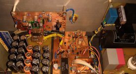
Before you start making the PCB, arrange the elements of the PLL filter a little, try to make them exactly according to the DS, as close as possible to the DIR itself with SMD components.
The picture shows my prototype PCB for dir9001, the regulators are three ADP7118, two for dir9001 and one for spdif receiver.
The picture shows my prototype PCB for dir9001, the regulators are three ADP7118, two for dir9001 and one for spdif receiver.
Attachments
Thanks again for your interest , I change things the best I could , now the regs are 4 mm away from the DIR 9001 , I use the TI evaluation board as an exemple , where they use film caps at pin 22 , There may be a good reason for that , that is what I thougt

.
.
Last edited:
- Home
- Source & Line
- Digital Line Level
- Building the ultimate NOS DAC using TDA1541A