Pedja still have the boards for sale I believe Hanze. Well I have 2 Aya one almost fully build. Lol. The nice thing about focusing just on 1 dac is that it allows one to experiment lot's & discover the pros & cons on tweaks that we make & to see how far an improvement we can attain over stock. . Hence who knows Johns pcb may have a different sound to Pedja's .
Cheers
Cheers
It works!
Our Guru did it again. 😀
😀
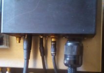
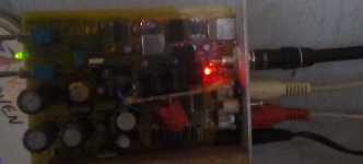
I modded a digital SPDIF cable with a miniature red LED instead of the usual connector and voilà! Signal locked! 😎
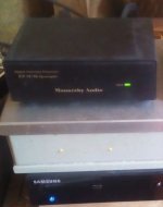
I used a modded transport in the form of a Bluray player to which I added an SPDIF output fed from the digital optic circuit: last time I checked, it produces a big signal, around 5V. Not perfect but it works. Now this SPDIF digital cable produces an optic signal through my cable which is fed to the Monarchy DIP Upsampler--> M-Audio SuperDAC-->TVC--> Amnesis amp...all galvanicaly insulated now.
Sweet music.
How did it take "us" so long to figure this out??? 😀
Cheers,
M.
Our Guru did it again.
😀I modded a digital SPDIF cable with a miniature red LED instead of the usual connector and voilà! Signal locked! 😎
I used a modded transport in the form of a Bluray player to which I added an SPDIF output fed from the digital optic circuit: last time I checked, it produces a big signal, around 5V. Not perfect but it works. Now this SPDIF digital cable produces an optic signal through my cable which is fed to the Monarchy DIP Upsampler--> M-Audio SuperDAC-->TVC--> Amnesis amp...all galvanicaly insulated now.
Sweet music.
How did it take "us" so long to figure this out??? 😀
Cheers,
M.
Attachments
Big Ground loops is a huge Ennemy... btw also locals around the 3 voltages pins and the ground references of the 1541 chip, others tda chips but the tda1540 are also simplier to work with because of that...
What specifically is expected to be accomplished and how? And what actually is accomplished after nearly fourteen years and seven thousand five hundred posts? (If I may ask).
What specifically is expected to be accomplished and how? And what actually is accomplished after nearly fourteen years and seven thousand five hundred posts? (If I may ask).
We are all (even if not consciously, for some) looking for spiritual enlightenment through musical bliss, at home, disguised as endless endeavors searching for satisfactory sounding equipment...
I thought all this was clear by now... 😀
Best wishes of joyful experiences to you all.
M.
BTW: this DIY chimeric digital cable "sounds" rather good. I wonder where John bought that "high speed LED".
I always feel that at least for Red Book playback there's still life in it which has yet to be fully capitalized.
Indeed. Red book sounding good here. 🙂
Talking about significant coincidences, a friend and I were commenting about personal projects and he declared himself owner of a 3D printer. Now I realize that the optimal connector for the chimeric DIY digital electrical-to-optical (not to use John's brand name) is to be 3D printed to accept LED and to make perfect fit onto the input receiver connector. 😎
Cheers,
M.
Attachments

I can now confirm that the board from JLsounds - I2SoverUSB v.III - works fine in simultaneous mode. It includes also the nice Thesycon USB driver with ASIO support.
Have you placed any resistors on the lines between i2soverusb and TDA1541A inputs, or they are directly wired?
Thanks,
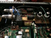
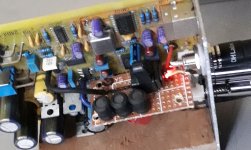
Here is my 1541A DAC. 12B4 hybrid shunt regulator (adj), TDA direct to D3a biased by DAC offset current, cathode to signal common, 80% nickel cored OPT 2:1 >2vRMS at <600 ohm out.
HK
HK
Attachments
Last edited:
Nice. 
Following with the "Electro-Optic link", not to use John's proprietary name 😀, and which must be the discovery/invention of the decade, I will comment that I have been thinking about ways to improve the mechanical execution of the same.
For example, instead of 3D printing a special connector, I will try those "micro to standard optic adapters", which I believe, have a small fiber optic path to reach near the receiver photo-diode...anyway, I am waiting for their arrival.
I did the following experiment as prove of concept:
1) I modded an old DVD player by making an extra electronic digital output taking the signal from the signal path for the Toslink transmitter.
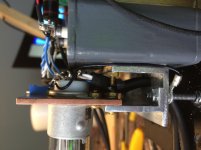
2) I modded a cheap DAC (Wolfson DAC chip; maybe 8840...; eBay of course) by installing a TORX177 optical receiver in the signal path. Then I connected the (new) electronic digital signal RCA connector to a miniature red LED. To improve the mechanical connection to the TORX177 receiver, I drilled the protector cap for the receiver and now the LED rests (partially) inside it, in a stable position, firmly connected to the TORX177.
3) I use a common SPDIF digital cable to connect both units.
It worked. 😎
Even while I am sure my technical execution is far from optimal, it worked, and not only that but also it sounds good, better than stock, with the same effect that on my other system. In a word: limpid.
This is most recommended experiment/mod.
Now I wish to make something alike for the MOSAIC DAC. 🙁
Sorry, my camera is behaving poorly...I will make a diagram latter.
Best wishes,
M.
Following with the "Electro-Optic link", not to use John's proprietary name 😀, and which must be the discovery/invention of the decade, I will comment that I have been thinking about ways to improve the mechanical execution of the same.
For example, instead of 3D printing a special connector, I will try those "micro to standard optic adapters", which I believe, have a small fiber optic path to reach near the receiver photo-diode...anyway, I am waiting for their arrival.
I did the following experiment as prove of concept:
1) I modded an old DVD player by making an extra electronic digital output taking the signal from the signal path for the Toslink transmitter.
2) I modded a cheap DAC (Wolfson DAC chip; maybe 8840...; eBay of course) by installing a TORX177 optical receiver in the signal path. Then I connected the (new) electronic digital signal RCA connector to a miniature red LED. To improve the mechanical connection to the TORX177 receiver, I drilled the protector cap for the receiver and now the LED rests (partially) inside it, in a stable position, firmly connected to the TORX177.
3) I use a common SPDIF digital cable to connect both units.
It worked. 😎
Even while I am sure my technical execution is far from optimal, it worked, and not only that but also it sounds good, better than stock, with the same effect that on my other system. In a word: limpid.
This is most recommended experiment/mod.
Now I wish to make something alike for the MOSAIC DAC. 🙁
Sorry, my camera is behaving poorly...I will make a diagram latter.
Best wishes,
M.
Attachments
Last edited:
I love you Max
I was about to say the same.
I love electronics.
I love music.
I love experimenting.
I love our accelerated evolution.
I love the coming new Golden Age.
I love you ALL, my friends and brothers.
Edit: hint about why these crazy guys are talking like 12 old girls... Schumann Resonance Today - Disclosure News Italia
*I posted another pic...
Forget about digititis and use this ElectrOptic linkk!
This post is charged with my Pure Divine Unconditional Love.
M.
PS: this DAC has no right to sound so good...
Last edited:
Max, you are a dreamer and un généreux philanthrope - a beautiful combination. (But I would not buy your amplifiers).
¤
Hey, why not build a nonoversampling 44 / 16 DAC with a decent power supply? It won`t get any better. Leave the DEM technique where it belongs: to the cheap oversampling delta-sigma DAC.
¤
Hey, why not build a nonoversampling 44 / 16 DAC with a decent power supply? It won`t get any better. Leave the DEM technique where it belongs: to the cheap oversampling delta-sigma DAC.
Max, you are a dreamer and un généreux philanthrope - a beautiful combination. (But I would not buy your amplifiers).
¤
Hey, why not build a nonoversampling 44 / 16 DAC with a decent power supply? It won`t get any better. Leave the DEM technique where it belongs: to the cheap oversampling delta-sigma DAC.
Then, I have to offer you one as a gift. 😀 Note that Imagination (the capacity of creating images) is our most powerful tool. 😉
I have several NOS DACs, thanks to John's generosity and unlimited creativity, with huge PS (I hate that word; did I mention it?) already. And they sound good.
Anyway, here goes the circuit. I accept remarks in order to perfect it.
Note that you also can flip an existing optical receiver...
BOM:
*1 mini LED USD$ 0.1
*1 TORX optical receiver USD$ 4.
*1 RCA connector USD$ 1.
*1 XR7 0u1 cap USD$ 0.1.
*1 47uH inductor USD$ 1.
*spare cable.
--------------------------------------
= we dreamers are not good at Maths...😀
Attachments

Last edited:
Well, actually 2 RCA connectors are needed, unless you re-purpose an existing one...if you are cheap like me. Suddenly, it is not that an inexpensive mod. 😀
Me think the Hanse tda1541a is certainly singing better than the AMR flagship, yah... 20 years of dev... nos tubes best OT man can find, pedja rogic core pcb for the double crown singapour tda1541a, iancanada Fifo and clock, shieldings everywhere...best crystal of Pulsar Clock...high qualities powersupplies...
I always said Max should try the tda1541...he has the r2r discrete dac from John to benchmark 🙂
I always said Max should try the tda1541...he has the r2r discrete dac from John to benchmark 🙂
Btw, Max, do you tried usb inputt with the wifj or bluetooth nano usb receiver...should not need of too much mA ? cost nothing and have a buffer also...? Sort of galvanic isolation but far less power needs than mini wifi receivers some tried to swap the usb cable ?
Also I see Rogic on Audial blog imputed about usb cables and a simple resistor for the usb ground ? John and Pedja have lot of usefull ideas...
Also I see Rogic on Audial blog imputed about usb cables and a simple resistor for the usb ground ? John and Pedja have lot of usefull ideas...
- Home
- Source & Line
- Digital Line Level
- Building the ultimate NOS DAC using TDA1541A