Great to hear you could use my suggestions
Hi could someone draw exact diagram what should be done. And i n what specific mode. Because many users have Ians FIFO.
Thanks
?
Hi could someone draw exact diagram what should be done. And i n what specific mode. Because many users have Ians FIFO.
Thanks
?
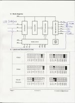
Here you go. I hope this is clear enough. The jumper setting is of course as shown for TDA1541
Attachments
Here you go. I hope this is clear enough. The jumper setting is of course as shown for TDA1541
If you have a FIFO you can use LE out of the FIFO clock board’s second set of i2s outputs (first set going to the i2s2pcm ofc).
Hi N101N,
- High accuracy of the 6 MSBs by means of the Dynamic Element Matching System.
The DEM clock (and external timing components) drive this DEM system and therefore have major impact on accuracy and DEM matrix switching noise levels.
- The ripple current introduced by the DEM system as a result of element mismatch, is filtered by a number of external filter caps (RC filter). These filter caps are part of the DEM system and therefore also have major impact on DEM accuracy and noise (ripple).
The original DEM timing operates at radio frequencies (200 ... 250 KHz) and therefore introduces major problems like injection locking / injection pulling, increased on-chip jitter, switching noise and external filter issues (PCB routing, filter cap RF properties).
- The 50Hz DEM and or DEM clock synchronisation with fs helps to maximise DEM accuracy and minimise DEM matrix switching noise on the TDA1541A outputs.
If you are referring to the simultaneous operation:
- Dedicated sample timing signal (LE) allows for lower jitter.
- Doubling the sample rate compared to I2S operation.
- Data switching noise reduction (clock stopping).
If you are referring to the "signed magnitude" TDA1541A configuration:
- All advantages of simultaneous operation plus:
- Major code change is moved out of the signal zero crossing range and its amplitude is halved.
- Glitch / error around the signal zero crossing is reduced.
- Output impedance is halved.
- Bit errors are averaged.
Hi, could these questions be answered briefly without elaboration:
What is the technical explanation for the TDA1541's excellence?
- High accuracy of the 6 MSBs by means of the Dynamic Element Matching System.
The DEM clock (and external timing components) drive this DEM system and therefore have major impact on accuracy and DEM matrix switching noise levels.
- The ripple current introduced by the DEM system as a result of element mismatch, is filtered by a number of external filter caps (RC filter). These filter caps are part of the DEM system and therefore also have major impact on DEM accuracy and noise (ripple).
The original DEM timing operates at radio frequencies (200 ... 250 KHz) and therefore introduces major problems like injection locking / injection pulling, increased on-chip jitter, switching noise and external filter issues (PCB routing, filter cap RF properties).
- The 50Hz DEM and or DEM clock synchronisation with fs helps to maximise DEM accuracy and minimise DEM matrix switching noise on the TDA1541A outputs.
What are the principles of the present design?
If you are referring to the simultaneous operation:
- Dedicated sample timing signal (LE) allows for lower jitter.
- Doubling the sample rate compared to I2S operation.
- Data switching noise reduction (clock stopping).
If you are referring to the "signed magnitude" TDA1541A configuration:
- All advantages of simultaneous operation plus:
- Major code change is moved out of the signal zero crossing range and its amplitude is halved.
- Glitch / error around the signal zero crossing is reduced.
- Output impedance is halved.
- Bit errors are averaged.
Here you go. I hope this is clear enough. The jumper setting is of course as shown for TDA1541
Hi, thanks 🙂
This is for 2 x TDA1541A? One chip per chanel -data/+data to inputs of L/R per chip, in Simoultaneous mode (pin27=-5V), right?
.
Can I suggest to add 2 x inverter (or 4x) in WS(LE) line for compensate eventual delay?
.
BTW I am "vintage" too about 52-53 I don't know any more...😕 And I have for years Ians boards, but I didn't connect pcbs yet... shame
Yes it is for two TDA1541A balanced in simultaneous mode, but you can use just one also and then only connect Dr+ and Dl+ .
There is no reason to delay the LE as it goes high long after the clock has stopped. One of the main features in the suggested change. See post 6662.
Here you can see that the clock has been silent for quite some time before LE goes high.
Even though I am old, i can still remember, that I am from June 3. 1952 ;-)
Last edited:
John,@EcDesign.
John, you must have followed the past discussions.
What to your opinion should a -90.3dBFS signal look like at the dac's output.
I would expect to see the usual three step square wave, but the image that Koldby showed is nothing alike
Building the ultimate NOS DAC using TDA1541A
Is that the way it should be with a TDA1541 or has it to do with meticulous separating Dgnd and Agnd and using solid ground planes that we don't see the three steps ?
Hans
You probably overlooked the above posting from a few weeks ago, but could you be so kind to answer my question ?
Thanks in advance,
Hans
If you have a FIFO you can use LE out of the FIFO clock board’s second set of i2s outputs (first set going to the i2s2pcm ofc).
Hi Thanks for the tip 🙂
Yes it is for two TDA1541A balanced in simultaneous mode, but you can use just one also and then only connect Dr+ and Dl+ .
There is no reason to delay the LE as it goes high long after the clock has stopped. One of the main features in the suggested change. See post 6662.
Here you can see that the clock has been silent for quite some time before LE goes high.
Even though I am old, i can still remember, that I am from June 3. 1952 ;-)
Yes, thanks for additional infos.
(Ha ha... I am from late 1966 it is about 52 for me, and i am consider my self old too 😛, anyway it is good to know we have experienced members, who remember decent and solid sound... Cheers 😉)
I got some inverter boards made for bclk will give it a go soon - the LE mod made an audible difference - I was surprised one LSB mattered...
Well I think it is more a matter of the time that goes from the CLK stops and to the LE goes positive. This is one of the main reasons for ecdesigns to suggest stopped clock operation.I got some inverter boards made for bclk will give it a go soon - the LE mod made an audible difference - I was surprised one LSB mattered...
Well I think it is more a matter of the time that goes from the CLK stops and to the LE goes positive. This is one of the main reasons for ecdesigns to suggest stopped clock operation.
Yeh fair point 🙂
2x tda1541a S2 on eBay at the mo’. £30 + Postage from China. Anyone want to give that a go? :b
I am from late 1966 it is about 52 for me, and i am consider my self old too 😛, anyway it is good to know we have experienced members, who remember decent and solid sound... Cheers 😉)
Year 1966 was a good year to re-enter: the Year of the Horse of Fire. 😎
Not only it is about remembering decent sound but it is also about caring for decent sound, something that most youths doesn't seem to care at all... 😱
Cheers,
M.
And a lot of decent recordings of classical music from the big companies RCA- EMI -Decca and (not so big) Mercury..Year 1966 was a good year to re-enter: the Year of the Horse of Fire. 😎
Not only it is about remembering decent sound but it is also about caring for decent sound, something that most youths doesn't seem to care at all... 😱
Cheers,
M.
Just an update inverted bclk from Ian’s Board doesn’t seem to work I get no sound. I suspect it’s due to the clock staying high instead of low when it’s stopped?
Just an update inverted bclk from Ian’s Board doesn’t seem to work I get no sound. I suspect it’s due to the clock staying high instead of low when it’s stopped?
That should not be a problem, as it is the transition from high to low that moves the data into the register..
BUT--- I don't recall that I have actually tried to invert the clk. I only tested the LE mod. So if it works without inverting the clk, I guess there is no reason to tamper with it. It was 3lite that suggested the clk should be inverted.
Yeh more logic required - I’ve since disabled it and things are working again.
Suspect it’s the initial falling edge when the clock stream starts post-inversion that’s making a mess of things...
Any ideas for keeping clock signal low until pulse train starts (stopped clock mode)? Thinking a d-flip flop is required...
I should leave it alone, but i have itchy fingers 😛
I took a look at the TDA1541A data sheet and it is quite obvious, that the CLK needs to be low before the LE is active.
I cannot think of an easy way to overcome this right out of my head, but I guess some of the algebra wizards here can 😀
Attachments
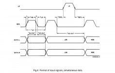
I took a look at the TDA1541A data sheet and it is quite obvious, that the CLK needs to be low before the LE is active.
I cannot think of an easy way to overcome this right out of my head, but I guess some of the algebra wizards here can 😀
Ahh i see, moving on - my next tweak is 50 hz DEM 😛
- Home
- Source & Line
- Digital Line Level
- Building the ultimate NOS DAC using TDA1541A