The use of 3mm mini jack is hilarious for a high grade product. May I suggest Lemo #00?
http://www.lemo.com/en/miniature-connector/00-connector
Sorry, but we do not discuss a coaxial cable - another beer.
Cheers,
That 's even more hilariousSorry, but we do not discuss a coaxial cable - another beer.
Cheers,
What about Eddy currents - still low nevertheless many strands ?
Regards,
Ignat
EC is worried by Eddy currents on the big connector's mass...
QSerra,
We are glad that this thread gets you on the mood 😀
Cheers,
M.
EC is worried by Eddy currents on the big connector's mass...
QSerra,
We are glad that this thread gets you on the mood 😀
Cheers,
M.
Nonsense, and the Lemos are also small.
EC is worried by Eddy currents on the big connector's mass...
/QUOTE]
Thanks your comments, I presume the mass of the conductors as well since the induction depends on that - or I am wrong.
Regards,
The conductors, being very thin, linear and independent would have very low Eddy as their individual surface for a loop is very small, and the current that runs inside the interconnect is divided by the number of individual strands...not to mention the electromagnetic influence of neighboring strands, whose effect escapes me... 😀
Edit: see Hall effect. I predict nullification of hall effect due to neighboring strands and chance...
Wikipedia is your friend...
Edit: see Hall effect. I predict nullification of hall effect due to neighboring strands and chance...
Wikipedia is your friend...
Last edited:
EC is worried by Eddy currents on the big connector's mass...
M.
Seems I am on the wrong side again ordering these - 2pcs Copper Gold Plated 3.5mm mono Mini Jack Plug soldering connector | eBay may be too big connectors mass
Please comment,
Thanks
Those are mono...you need stereo.
At the end, the area of the loop is what matters, apart mass itself. Shorter loop is better.
Maybe -EC- would like to comment about this.
Cheers,
M.
At the end, the area of the loop is what matters, apart mass itself. Shorter loop is better.
Maybe -EC- would like to comment about this.
Cheers,
M.
Hi niamex,
Use two separate litz wire strands, one for L channel (15 x GND plus 1 signal wire) and one for R channel (15 x GND plus 1 signal wire).
Maxlorenz has a point about static charge on plastic insulators. If this plastic is located between signal wire and GND it could lead to effects similar as with a condensor microphone when GND and signal wire can move and a static charge is present on the plastic insulator.
One can check if there is a problem with static charge by connecting the interlink to the power amp only and then move around the interlink. If you hear a crackling sound there is a problem with static charge. This could become a problem when the interlink resonates with the air pressure waves generated by the speakers. Similar effect can be heard with some microphone and electrical guitar interlinks where this effect is greatly amplified.
But here the signal wire is embedded in 15 GND wires so there is no extra plastic insulator between the wires, only around the complete strand so this should be no problem.
However, if you want to be absolutely sure, use a cotton sleeve around each strand of wires. Cotton has least problems with static charge, PTFE is much worse:
https://jh399.k12.sd.us/dailyassign/physics/ch7materialstaticelec.pdf
You have to look where the signal flows and how much mass is in series with this signal path. So a connector can have a solid metal housing but as long as the signal does not flow through it, there is no problem.
Most 3.5mm plugs have to be manufactured in a specific way:
http://i01.i.aliimg.com/img/pb/690/540/636/636540690_657.JPG
This leads to low Eddy current losses, that’s why I use these standard audio connectors. When good quality plugs and sockets are used there is no problem with contacts either.
Avoid 3.5mm sockets that have no spring contact on the GND terminal, these will develop poor contact.
I suggest to try Neutrik (Rean) connectors. These have good build quality and low price.
Eddy current losses would be no problem when losses are exactly the same for all frequencies and currents.
Unfortunately Eddy current losses increase with both, frequency and current. So audio signals become distorted by Eddy current losses and that’s the main problem.
The skin effect is a different problem where the electrical charge mainly flows through the outer part (skin) of the conductor, this happens at much higher frequencies. We already have Eddy current losses at low frequencies, mains transformers where laminated cores are required to reduce Eddy current losses run at 50 or 60 Hz.
Eddy current distortion doesn't stop at the interlinks. It also occurs in internal wiring and circuits of audio components.
Hi John,
Since there was no comment on my question I have made the stereo cable as above - so far so good, the highs became more readable at their top end /considered as drawback of the 1541/ but still I have some suspicions there could be some interference between the two channels so close each to other in the cable. There will be no problem to prepare a new cable 15 + 1 and separate the two channels and try if you suggest so - please comment
Cheers,
Use two separate litz wire strands, one for L channel (15 x GND plus 1 signal wire) and one for R channel (15 x GND plus 1 signal wire).
Maxlorenz has a point about static charge on plastic insulators. If this plastic is located between signal wire and GND it could lead to effects similar as with a condensor microphone when GND and signal wire can move and a static charge is present on the plastic insulator.
One can check if there is a problem with static charge by connecting the interlink to the power amp only and then move around the interlink. If you hear a crackling sound there is a problem with static charge. This could become a problem when the interlink resonates with the air pressure waves generated by the speakers. Similar effect can be heard with some microphone and electrical guitar interlinks where this effect is greatly amplified.
But here the signal wire is embedded in 15 GND wires so there is no extra plastic insulator between the wires, only around the complete strand so this should be no problem.
However, if you want to be absolutely sure, use a cotton sleeve around each strand of wires. Cotton has least problems with static charge, PTFE is much worse:
https://jh399.k12.sd.us/dailyassign/physics/ch7materialstaticelec.pdf
Seems I am on the wrong side again ordering these - 2pcs Copper Gold Plated 3.5mm mono Mini Jack Plug soldering connector | eBay may be too big connectors mass
Please comment,
Thanks
You have to look where the signal flows and how much mass is in series with this signal path. So a connector can have a solid metal housing but as long as the signal does not flow through it, there is no problem.
Most 3.5mm plugs have to be manufactured in a specific way:
http://i01.i.aliimg.com/img/pb/690/540/636/636540690_657.JPG
This leads to low Eddy current losses, that’s why I use these standard audio connectors. When good quality plugs and sockets are used there is no problem with contacts either.
Avoid 3.5mm sockets that have no spring contact on the GND terminal, these will develop poor contact.
I suggest to try Neutrik (Rean) connectors. These have good build quality and low price.
Eddy current losses would be no problem when losses are exactly the same for all frequencies and currents.
Unfortunately Eddy current losses increase with both, frequency and current. So audio signals become distorted by Eddy current losses and that’s the main problem.
The skin effect is a different problem where the electrical charge mainly flows through the outer part (skin) of the conductor, this happens at much higher frequencies. We already have Eddy current losses at low frequencies, mains transformers where laminated cores are required to reduce Eddy current losses run at 50 or 60 Hz.
Eddy current distortion doesn't stop at the interlinks. It also occurs in internal wiring and circuits of audio components.
Hi maxlorenx,
http://sound.westhost.com/xfmr11-4.gif
This picture shows Eddy currents in materials with different lamination.
Something similar happens when using increasing amount of thinner insulated wires in parallel that offer the same DC resistance as a solid core wire.
Ground loops take the path of lowest resistance and this is usually the GND wire of the interlink.
In order to minimise unwanted ac voltage drop across the GND wire (ground loops) it needs to have low impedance. This is one reason why I used 15 wires in parallel for GND and only a single wire for the signal. If this is not enough one can simply add more insulated wires for GND.
The single, thin signal wire has small surface area so when it is embedded in the GND wire strand, stray capacity will be relatively low. When we increase the number of signal wires embedded in the strand (say 15 GND strands and 15 signal strands) we would have a problem with too high stray capacitance.
At the end, the area of the loop is what matters, apart mass itself. Shorter loop is better.
http://sound.westhost.com/xfmr11-4.gif
This picture shows Eddy currents in materials with different lamination.
Something similar happens when using increasing amount of thinner insulated wires in parallel that offer the same DC resistance as a solid core wire.
Ground loops take the path of lowest resistance and this is usually the GND wire of the interlink.
In order to minimise unwanted ac voltage drop across the GND wire (ground loops) it needs to have low impedance. This is one reason why I used 15 wires in parallel for GND and only a single wire for the signal. If this is not enough one can simply add more insulated wires for GND.
The single, thin signal wire has small surface area so when it is embedded in the GND wire strand, stray capacity will be relatively low. When we increase the number of signal wires embedded in the strand (say 15 GND strands and 15 signal strands) we would have a problem with too high stray capacitance.
Hi niamex,
Use two separate litz wire strands, one for L channel (15 x GND plus 1 signal wire) and one for R channel (15 x GND plus 1 signal wire)............
Hi John,
Many thanks for profound lectures !
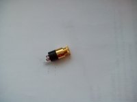
Based on them will try cable 20+1 /20 strands are twisted already as bought/. Neutrik jack is here, the sockets not clear whether have spring inside - attached pic.,ordered cotton shoe laces. Two separate cables - left and right ??
I believe your and Maxlorenz tutorials are of great help to enthusiasts.
Cheers,
Ignat
Attachments
Hi Niamex,
When the supplier includes a mechanical drawing, this can usually be verified. Otherwise you have to break open a socket and check for yourself.
I use these sockets in the new Mosaic T DAC and the Mosaic VC volume controller:
http://static1.tme.eu/products_pics...presentation/prime_presentation_pres_0000.jpg
On the photograph you can see the GND contact spring at the bottom.
For the new Equilibrium ZF (Zero global Feedback) I plan to use these:
NYS240BG - REAN Connectors
This socket has gold plated contacts. When studying the mechanical drawing you can see the GND spring.
Neutrik jack is here, the sockets not clear whether have spring inside
When the supplier includes a mechanical drawing, this can usually be verified. Otherwise you have to break open a socket and check for yourself.
I use these sockets in the new Mosaic T DAC and the Mosaic VC volume controller:
http://static1.tme.eu/products_pics...presentation/prime_presentation_pres_0000.jpg
On the photograph you can see the GND contact spring at the bottom.
For the new Equilibrium ZF (Zero global Feedback) I plan to use these:
NYS240BG - REAN Connectors
This socket has gold plated contacts. When studying the mechanical drawing you can see the GND spring.
Contact resistance?Hi Niamex,
When the supplier includes a mechanical drawing, this can usually be verified. Otherwise you have to break open a socket and check for yourself.
I use these sockets in the new Mosaic T DAC and the Mosaic VC volume controller:
http://static1.tme.eu/products_pics...presentation/prime_presentation_pres_0000.jpg
On the photograph you can see the GND contact spring at the bottom.
For the new Equilibrium ZF (Zero global Feedback) I plan to use these:
NYS240BG - REAN Connectors
This socket has gold plated contacts. When studying the mechanical drawing you can see the GND spring.
Poor
Well from experience I know contact reliability of the 3mm jack is VERY poor.
🙁
Contact reliability.... 😉
Well from experience I know contact reliability of the 3mm jack is VERY poor.
🙁
ecdesigns; When the supplier includes a mechanical drawing said:I have decided to go this way, using the contact with less mass for the signal and providing an additional ground spring contact.
Cheers,
Attachments

I have decided to go this way, using the contact with less mass for the signal and providing an additional ground spring contact.
Cheers,
Your contact resistance: 50 mOhm
Lemo: 5 mOhm
Thanks, you may be right - I am not very good at it so will wait for comments.Your contact resistance: 50 mOhm
Lemo: 5 mOhm
Hi QSerraTico_Tico
Yep, the ground contact issue, that’s why I use a version with GND contact spring as I already mentioned.
From the Lumberg datasheet:
http://www.farnell.com/datasheets/71579.pdf
Contact resistance <= 30 mOhm, not 50 mOhm.
With 5.65Vpp (2V rms) and 10K load we have a peak current of only 565uA and a voltage drop of only 16.95uV. The currents are very low, so we don’t need bulky connectors with very low contact resistance. What we need is lowest possible dynamic distortion and highest possible resolution at these low signal current levels.
Contact reliability, => 5000 mating cycles.
If you disconnect and reconnect these 3.5mm interlinks every day for whatever reason, these connectors will last at least 13 years. Similar connectors are also used in smartphones and pads, if these connectors are as unreliable as you claim, we would have heard about this for sure.
Well from experience I know contact reliability of the 3mm jack is VERY poor.
Yep, the ground contact issue, that’s why I use a version with GND contact spring as I already mentioned.
Your contact resistance: 50 mOhm
Lemo: 5 mOhm
From the Lumberg datasheet:
http://www.farnell.com/datasheets/71579.pdf
Contact resistance <= 30 mOhm, not 50 mOhm.
With 5.65Vpp (2V rms) and 10K load we have a peak current of only 565uA and a voltage drop of only 16.95uV. The currents are very low, so we don’t need bulky connectors with very low contact resistance. What we need is lowest possible dynamic distortion and highest possible resolution at these low signal current levels.
Contact reliability, => 5000 mating cycles.
If you disconnect and reconnect these 3.5mm interlinks every day for whatever reason, these connectors will last at least 13 years. Similar connectors are also used in smartphones and pads, if these connectors are as unreliable as you claim, we would have heard about this for sure.
- Home
- Source & Line
- Digital Line Level
- Building the ultimate NOS DAC using TDA1541A