No change to noise level during my experiments. Aluminum foil on DC to DC also didn’t change it.
Should I try higher inductance coils, and let’s say to double it? Also, my U4 has no sink yet and it is hot. It might be noise.. Board is not in grounded box and also it might picking up some RF... This ripples are in 100mv RMS window.
I’ll just mention that the B1Korg, which uses the same NuTube device, is in an unventilated chassis. That was chosen after early versions exhibited microphonics. Just FYI.
I personally do not like an idea of sealed enclosures. Could be very scary moments when your big Ele caps are pups up. Material, panels thicknesses and holes diameters are related to EMI attenuation. Please see: https://www.emcs.org/acstrial/newsletters/fall07/pg102-103.pdf.
I usually use (or drill if needed) 3.5-4mm dia holes in average on all my aluminum enclosures (for top and bot to allow convection) and didn't see any RF coupling yet even on my sensitive phono preamps. Magnetic coupling is defeated by Permalloy and I acquired once 0.3mmx600mmx1000mm sheet of Mu-Metal from Ukraine/Russia with MIL spec. So, time to time I do use its pieces.
I usually use (or drill if needed) 3.5-4mm dia holes in average on all my aluminum enclosures (for top and bot to allow convection) and didn't see any RF coupling yet even on my sensitive phono preamps. Magnetic coupling is defeated by Permalloy and I acquired once 0.3mmx600mmx1000mm sheet of Mu-Metal from Ukraine/Russia with MIL spec. So, time to time I do use its pieces.
When I experimented with this, I found that changing the filters didn't make a lot of difference. It seemed like most of the noise was radiated, not conducted. The thing that made the most difference was physically relocating the converter away from the rest of the circuit.
I also tried several different converters. The one I settled on was this:
https://www.mouser.com/ProductDetail/XP-Power/IE0505S/?qs=w/v1CP2dgqoXUua2Bslg5g==
I think it is a little better than the one I originally had on the BOM.
A metal chassis may help.
The reg does run hot, though within its limits. Many people shoehorn a small heatsink in to cool it.
Pete
Purchased these new converters and thank you for link. Also, will drop all PCBs into enclosure soon. Lets see then....
So glad I put this in a chassis with separate right and left volume pots. I can play with the NuTube plate voltages on one channel and compare it to the other instantly. Right now, with 221R resistors, I’m at about 5v on TP 3 and 6.5v on TP 5. Very nice. My top and bottom covers on my Galaxy 2 chassis have fairly limited ventilation slots, so once again I seem to have no noticeable microphonics from either tube. A question for anybody: If I want to check +/- signal voltage with R5 trimmer, where do I take my measurements? Gate of Q1 and Q2 maybe?
A question for anybody: If I want to check +/- signal voltage with R5 trimmer, where do I take my measurements? Gate of Q1 and Q2 maybe?
This is what discussed in thread#9 and I attached diagram about connections to thread #10.
So glad I put this in a chassis with separate right and left volume pots. I can play with the NuTube plate voltages on one channel and compare it to the other instantly. Right now, with 221R resistors, I’m at about 5v on TP 3 and 6.5v on TP 5. Very nice. My top and bottom covers on my Galaxy 2 chassis have fairly limited ventilation slots, so once again I seem to have no noticeable microphonics from either tube. A question for anybody: If I want to check +/- signal voltage with R5 trimmer, where do I take my measurements? Gate of Q1 and Q2 maybe?
Hi Jim,
Can you share the FFT here with the above TP3/TP5 readings?
In my case I have found different THD readings with the cover on and with it off and one tube is affected a lot more than the other.
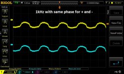
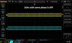
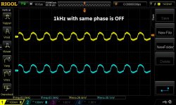
Regarding your CMRR question, I hook up Arta spectrum analysis, feed a 0.5v 1 khz signal only to + phase and see the balanced out on the FFT. Lets say I get -10db. I then switch the signal to only the - phase and again see the output. I see something close to -10db. Then I jumper the + to the - input and again read the output. I get -40db, which means I am getting a common mode rejection of 30db. Then adjust R5 to get the highest rejection db number. This does however change your FFT pattern, so you will have to readjustTP3/TP5 to get your desired picture. Ultimately I just set TP3 TP5 where I wanted it and left R5 around the middle.
nash
If I had an oscilloscope I certainly would, but I don’t. I thought about it, but after watching some of the Blueglow You Tube videos I decided not to spend the $ on the quality machine he was recommending. Thanks for your initial post on this preamp, by the way.
I dont have a scope either, at least not yet.
I am using a Focusrite 2i2 gen3 sound interface and free Arta software.
nash
I am using a Focusrite 2i2 gen3 sound interface and free Arta software.
nash
Installed IE0505S DC2DC and high frequency component is still there. Less jumpy output signal i general, but 80kHz is still there with about 80mV in average for RMS. Tried Mu Metal covers on these IE0505S and also on L1 and on L2 coils, and saw no impact.
So, I'm thinking about trying higher inductance coins anyway (in spite of your info about nature of airborne noise coupling). The problem is that coils have lead spacing equal to 2mm and the most of similar coils (I think about shielded once too) are 5mm lead spacing. There is only one coils from the same series that has same lead spacing is 11R474C with 470uH. Is any part that I missed will go to the same position with 600+uH? I see 22R684C, but it is 3mm and not shielded either....
Any way, I'm in waiting for enclosure which supposed to be here in 2 weeks. So, why now to spend that time for some trials...? 🙂
Tested with 1.5uH (22R155C) coils and still no significant change to 80kHz noise. Waiting for my box to arrive in a week or so and proper GNDing inside of it. Might be my boxing will reduce it. Let's see...
Attachments
Last edited:
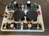
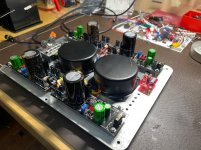
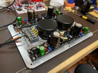
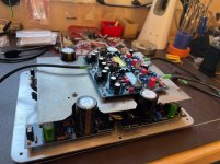
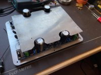
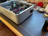
Finally, have my box arrived and I already started component assembly. Bottom part, witch is power section, is ready. Second floor will accommodate apm's PCBs and separation plate is made of 0.3mm Permalloy (Mu Metal).
Attachments
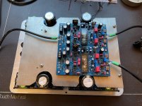
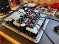

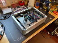
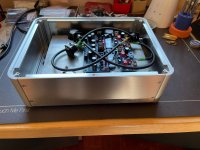
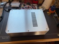
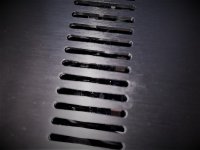
And here is with enclosure. Front and Back panels are not milled yet. Tried to make tubes to be visible through vents holes. Also, I'll add nice UV meters to the front.
Attachments
Looks good Alex.
Volume control?
nash
Thank you, Nash.
I purchased 47 steps quad 50k (recommended value by Pete) attenuator from Goldpoint. Expensive, but I use these in all my build and did not regret yet. I also tried Khozmo (ladder, relay based) and had huge GND loop issue that took me awhile to defeat.
Prices
All is boxed, but I'm still waiting for some enclosure related parts that must replace damage caused by shipping from eBay China. I settled with my setup and I'm running +/-14.80VDC on both channels. TP3 and TP5 are at 5.4VDC on both. All the rest of TPs values are at advertised ranges.
I have some GND loop (hope it is not my Ficusrite artifact). Please see attached Arta. Also, I have some imbalance and harmonics seems bit different on each channel.
Please advice if you know how to defeat these....
I have some GND loop (hope it is not my Ficusrite artifact). Please see attached Arta. Also, I have some imbalance and harmonics seems bit different on each channel.
Please advice if you know how to defeat these....
Attachments
Connected to balance source first time and I'm bit confused now. First of all, I hear no GND loop hum. Second, it is very quite at 2/3 of my total volume range (my headphones are 200R impedance and 130dB SPL). Farther volume increase creates obvious harsh and distortion.
Hmm, I checked all my setup measurements for sanity and I'm showing these values below. Each TP is measured with reference to GND and in RMS.
L channel:
PSU: +14.87/0/-14.88 VDC
T3 +5.425 VDC
T5 +5.456 VDC
T4 -14.09 VDC
T1 -12.20 VDC
T2 -12.66 VDC
R channel:
PSU: +14.88/0/-14.81 VDC
T3 +5.387 VDC
T5 +5.404 VDC
T4 -14.10 VDC
T1 -11.76 VDC
T2 -12.43 VDC
Do you guys see any obvious issue? Please let me know.
Hi Alex,
Good to see that you are up and running!
Firstly, have you connected your Focurite with bal in and bal out? I am using Focusrite gen3 bal in and out, feed 1v in by adjusting the Monitor knob and keeping the Gain knob completely off. and measure out thru Arta. If you can do likewise we can easily compare notes.
Can you feed 1v in and do a loopback and post the plot? This will tell us what residual to expect. Next keeping 1v in in all cases and using the volume attenuator of the preamp do plots around 1v, 0.5v, 0.25v and 0.12v. This shows the behavior as the volume is reduced. Ideally, around 0.12v out there will be very little H2 and no H3 and then as volume is increased H2 rises and then you see H2 and H3 and as output is further increased H3 rises much faster than H2. And, the two channels must look similar. In my case most of my serious listening is at around 0.12 to 0.20v attenuator positions. Please post these 4 plots.
Personally, I feel your THD levels are very high and quite a bit different from each other. I realize that you have set it to 5.4v specs each but as I mentioned earlier it does not work for me. Considerable twiddling is needed.
Regarding the 50hz spike have you added a resistor between the Ubib G to chassis?
The db difference between the two channels is to be expected but can be fixed easily later by padding the attenuator.
Nash
- Home
- Source & Line
- Analog Line Level
- Building the Pete Millett Korg Nutube Balanced Preamp