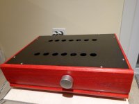
Here I will detail some of the construction details and set up of the Pete Millett Korg Nu tube Balanced preamp that I have built. Schematic is reproduced for convenience.
Jfets- I chose to use the Toshiba 2SK170BL for Q1 thru Q4. However, I did not have 16 matched ones, so I used the lower Idss values for the followers Q1A thru Q4A and the higher ones for the CCS Q1B thru Q4B with small degenerating resistors typically around 5r to get 0VDC offset. My Jfets were mostly in the 7-9ma range. I asked Pete “Could you please explain to me why you have chosen 1k source degeneration resistors (R6/R8, etc) in the Jfet followers as opposed to self biasing them without any?” His reply “Adding a resistor helps to stabilize the stage current without requiring selecting FETs for a particular current (they can vary a lot, maybe 2:1, without it). If the FETs are matched, the resistor on the upper FET also will give an output voltage equal to the input voltage, as the voltage drop on the two resistors will match.”
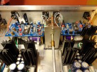
Capacitors C6, C7 and C13, C14- I wanted to use film caps from the get go but they are large so I asked whether smaller value caps could be used. Pete responded “The coupling caps are big largely to avoid bias shifts with the signal. Since the tube is in A2 and draws some grid current, using a lower cap will increase distortion because at low frequency the cap will discharge more on positive peaks than negative. So I wouldn't recommend going any lower.” I chose Clarity Cap CSA 12uf for the caps before the Nutube and CDE 940C caps for the ones after the tube. I mounted them under the PCB, as shown in the attached pic.
Microphony- The Nutube was mounted on top of a piece of foam mounting tape attached to the PCB. Additionally, each PCB and cap assembly was mounted using 40mm standoffs onto a base plate which in turn was attached to the chassis bottom plate with foam tape. The PSU’s and the transformers and stepped attenuator were also attached similarly. I cannot hear any pinging when turning the volume knob but you can clearly see it on display as spikes around 5khz when doing the THD plots if you tap on the case. I used the Salas DCSTB Psu’s at 15v output. Nice!
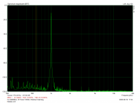
Set up – It took me a very long time, mostly due to inexperience, to get the plate voltage settings where they sounded best to me. I used my Focusrite 2i2 in balanced mode and ARTA software for the FFT plotting and set up. I finally decided on a setting where I could null both H2 and H3. From these null points, R12 was turned ACW to increase plate voltage to get H3 just a bit off its null and R13 was turned CW to decrease the plate voltage of its respective tube section to get H2 up where I want it. This gave the sound I was looking for with the resultant THD plots shown. The plots were done at 0.42V output after 2 hours warm-up using 332k plate resistors.. Here are the plate voltage readings:
L channel TP3 4.07V TP5 6.85V
R channel TP3 4.14V TP5 6.76V
Measured gain was 12.89db Left channel and 12.73db Right channel.
The above settings also result in “negative phase H2” as defined by Nelson Pass. The XLR output connector is normally connected to the PCB outputs i.e. PCB output+ and output_ are connected to XLR pins 2 and 3 respectively. To verify negative phase H2, I temporarily reversed output XLR 2 and 3 and easily noticed the sound had shifted forward. I much prefer negative phase H2.
Sound- I use this preamp to feed my Sony Vfet power amps and Troel Gravesen OBL 15 speakers. Compared to my BA3 and DCG3 balanced preamps the difference I find most striking is that each musical note sounds fuller yet is extremely clear. The other two preamps also sound clear but seem thin in comparison. If you increase H2 further the sound becomes more euphonic but gets muddier. It sounds better to my ears with a very low H3 and a much higher H2 than with a somewhat higher H3 and lower H2. Mention must be made that the overall setting is tuned to perform best with the Sony VFET amps. All three of my preamps throw a very large soundstage but the Nutube preamp sounds the most realistic, especially with classical. Late night listening at lower volumes is also very satisfying. To my great surprise even large scale orchestral works sound excellent.
Thanks to Pete Millett for a well designed, easy to assemble PCB. I like it that all the lettering on the PCB is outside the part outlines so that they are not obscured once the parts are stuffed. Thanks to Nelson Pass for his very informative articles on H2 and to Salas for the excellent DCSTB Psu’s and his ever willingness to answer any and all questions.
Jfets- I chose to use the Toshiba 2SK170BL for Q1 thru Q4. However, I did not have 16 matched ones, so I used the lower Idss values for the followers Q1A thru Q4A and the higher ones for the CCS Q1B thru Q4B with small degenerating resistors typically around 5r to get 0VDC offset. My Jfets were mostly in the 7-9ma range. I asked Pete “Could you please explain to me why you have chosen 1k source degeneration resistors (R6/R8, etc) in the Jfet followers as opposed to self biasing them without any?” His reply “Adding a resistor helps to stabilize the stage current without requiring selecting FETs for a particular current (they can vary a lot, maybe 2:1, without it). If the FETs are matched, the resistor on the upper FET also will give an output voltage equal to the input voltage, as the voltage drop on the two resistors will match.”
Capacitors C6, C7 and C13, C14- I wanted to use film caps from the get go but they are large so I asked whether smaller value caps could be used. Pete responded “The coupling caps are big largely to avoid bias shifts with the signal. Since the tube is in A2 and draws some grid current, using a lower cap will increase distortion because at low frequency the cap will discharge more on positive peaks than negative. So I wouldn't recommend going any lower.” I chose Clarity Cap CSA 12uf for the caps before the Nutube and CDE 940C caps for the ones after the tube. I mounted them under the PCB, as shown in the attached pic.
Microphony- The Nutube was mounted on top of a piece of foam mounting tape attached to the PCB. Additionally, each PCB and cap assembly was mounted using 40mm standoffs onto a base plate which in turn was attached to the chassis bottom plate with foam tape. The PSU’s and the transformers and stepped attenuator were also attached similarly. I cannot hear any pinging when turning the volume knob but you can clearly see it on display as spikes around 5khz when doing the THD plots if you tap on the case. I used the Salas DCSTB Psu’s at 15v output. Nice!
Set up – It took me a very long time, mostly due to inexperience, to get the plate voltage settings where they sounded best to me. I used my Focusrite 2i2 in balanced mode and ARTA software for the FFT plotting and set up. I finally decided on a setting where I could null both H2 and H3. From these null points, R12 was turned ACW to increase plate voltage to get H3 just a bit off its null and R13 was turned CW to decrease the plate voltage of its respective tube section to get H2 up where I want it. This gave the sound I was looking for with the resultant THD plots shown. The plots were done at 0.42V output after 2 hours warm-up using 332k plate resistors.. Here are the plate voltage readings:
L channel TP3 4.07V TP5 6.85V
R channel TP3 4.14V TP5 6.76V
Measured gain was 12.89db Left channel and 12.73db Right channel.
The above settings also result in “negative phase H2” as defined by Nelson Pass. The XLR output connector is normally connected to the PCB outputs i.e. PCB output+ and output_ are connected to XLR pins 2 and 3 respectively. To verify negative phase H2, I temporarily reversed output XLR 2 and 3 and easily noticed the sound had shifted forward. I much prefer negative phase H2.
Sound- I use this preamp to feed my Sony Vfet power amps and Troel Gravesen OBL 15 speakers. Compared to my BA3 and DCG3 balanced preamps the difference I find most striking is that each musical note sounds fuller yet is extremely clear. The other two preamps also sound clear but seem thin in comparison. If you increase H2 further the sound becomes more euphonic but gets muddier. It sounds better to my ears with a very low H3 and a much higher H2 than with a somewhat higher H3 and lower H2. Mention must be made that the overall setting is tuned to perform best with the Sony VFET amps. All three of my preamps throw a very large soundstage but the Nutube preamp sounds the most realistic, especially with classical. Late night listening at lower volumes is also very satisfying. To my great surprise even large scale orchestral works sound excellent.
Thanks to Pete Millett for a well designed, easy to assemble PCB. I like it that all the lettering on the PCB is outside the part outlines so that they are not obscured once the parts are stuffed. Thanks to Nelson Pass for his very informative articles on H2 and to Salas for the excellent DCSTB Psu’s and his ever willingness to answer any and all questions.
Attachments

Excellent post and a lot of interesting aspects. I just assembled same kit and I also use Salas’s designed PSU. That time is two separate + and - UBIBs units. Two small Triad 2x15V on secondaries (0.8A) toroids feed these PSUs. R19 and R20 are occupied with 221K. I set Bias (TP3 and TP5) to 5.46VDC. Tried to be very equal there. All the rest of TPs are measured in suggested in schematic range.
Now, I’m struggling to adjust balance. I’m sending two identical 1kHz 1VRMS sinuses, but output looks the same in spite of trimmer turns. May be I didn’t connect my scope correctly to output (not familiar with balanced yet)... So, I connected my DVM meter instead to + and -. Same phase sinuses on input gave 2.4VRMS (no change when I turn balance trimmer up/down). 0 and 180 sinuses on input gave me 7.6VDC on output. It seems like voltage gain is works, but no balance.... Can you please advice how to get that step done?
Now, I’m struggling to adjust balance. I’m sending two identical 1kHz 1VRMS sinuses, but output looks the same in spite of trimmer turns. May be I didn’t connect my scope correctly to output (not familiar with balanced yet)... So, I connected my DVM meter instead to + and -. Same phase sinuses on input gave 2.4VRMS (no change when I turn balance trimmer up/down). 0 and 180 sinuses on input gave me 7.6VDC on output. It seems like voltage gain is works, but no balance.... Can you please advice how to get that step done?
I also recently finished Pete’s preamp boards. Unlike Alexkosha, I am unable to get bias at both plates to the recommended 5.4v using the 221k resistors. Instead, I’m getting values closer to nashbap’s tunings, as adjusting each plate affects the other plate. Other voltage readings are correct. Using a Pete’s ops plan power supply and getting 15x + -. I haven’t gotten to balance yet, but do have separate volume pots for each channel in my chassis.
I also see that +/- Biases dependence to each other, but I got some equilibrium. Have you shorted + and - inputs to GND during adjustment?
I have balanced Gildpoint 50k attenuator, but didn’t install it yet.
My output sinuses looks off and I need to learn how to connect scope to balanced outputs correctly. I also will use Focusrite balanced, but need to make cables first...
I have balanced Gildpoint 50k attenuator, but didn’t install it yet.
My output sinuses looks off and I need to learn how to connect scope to balanced outputs correctly. I also will use Focusrite balanced, but need to make cables first...
I also recently finished Pete’s preamp boards. Unlike Alexkosha, I am unable to get bias at both plates to the recommended 5.4v using the 221k resistors. Instead, I’m getting values closer to nashbap’s tunings, as adjusting each plate affects the other plate. Other voltage readings are correct. Using a Pete’s ops plan power supply and getting 15x + -. I haven’t gotten to balance yet, but do have separate volume pots for each channel in my chassis.
I meant R5 balance for + and - on the same board. Not balance between R and L channels witch you can achieve with separate pots as you mentioned.
Hi Alex and Jim,
Good to see you here.
Firstly an update from my end; I switched from Salas DCSTB to Ubib1.3 one per channel for a noticeable improvement in sound.
Alex, R5 is to reduce CMRR to the minimum. Send a signal say 1v 1khz to the + phase and then jumper the + phase to the -phase so that each phase sees the same signal which will then be common to both. Technically this should result in a very low output, and you adjust R5 to get the lowest.
Jim, each pot effects the other. If you want to get a high H2 and a very low H3 with negative phase H2, then follow my setup as above. Over the months I have experimented a lot and I find that a THD or around 0.035 to 0.040% sounds best overall. This is at 1v in 1khz and using the attenuator of the amp outputting roughly 0.42v. I found that I could match the two channel spectra quite closely at this level and below but not at the higher 1v out level as done by NP in his B1K. I felt that matching at a bit lower level was more important to me since the gain here is high so the lower output levels are more important.
Get both TP3 and TP5 nulled as low as possible, then first adjust TP5 in the direction noted above to bump up H2 to the THD desired, then readjust TP3 a bit to null H3 and keep H2 high. All of this around 0.4-0.5V out. I find that if your TP3, TP5 null readings are good the TP5 does not make TP3 move that much once you are in the desired THD range. Also note that these readings do change as the amp gets warmed up so best to adjust after an hour at least.
Keep us posted.
nash
Hi Nash, thank you for reply.
I see your TP3 and TP5 are quite differ from each other and therefore it is strange that Pete mentioned about necessity of close as possible proximity for TP3 and TP5 (matching).
Also, and at least for me, I need to align about our terminology. What parameter did you call as H2/3?
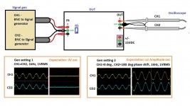
I made simple diagram for CMRR test setup. Please take a look.
I use two channels Gen where CH1=CH2, but you are right and same phase input can be set by short jumper between + and – on input.
As I mentioned before, so far my output is still about 2.4 VRMS with synced inputs and I can’t null it down farther. However, I didn’t use any load by now, but will try to add one today.
200R will be desired since it will simulate one of my headphones.
I see your U4 has sink. So, my U4 is also fairly warm and I need to add some one-side flat heat sink too. Will search for one soon.
Alex
I see your TP3 and TP5 are quite differ from each other and therefore it is strange that Pete mentioned about necessity of close as possible proximity for TP3 and TP5 (matching).
Also, and at least for me, I need to align about our terminology. What parameter did you call as H2/3?
I made simple diagram for CMRR test setup. Please take a look.
I use two channels Gen where CH1=CH2, but you are right and same phase input can be set by short jumper between + and – on input.
As I mentioned before, so far my output is still about 2.4 VRMS with synced inputs and I can’t null it down farther. However, I didn’t use any load by now, but will try to add one today.
200R will be desired since it will simulate one of my headphones.
I see your U4 has sink. So, my U4 is also fairly warm and I need to add some one-side flat heat sink too. Will search for one soon.
Alex
Attachments
Hi guys -
On the plate voltage... the exact voltage isn't all that important. On most nutubes with 221k plate resistors, you may hit the limit of the bias pots before getting to 5.4V. 5v or 6V is fine. You should adjust to get the two voltages close to each other, assuming you want minimum distortion, especially minimal 2nd harmonic. They do interact, since the CCS in the tail means that if you raise the current through one half, you will lower it in the other.
If you want to intentionally add 2nd harmonic, then you can skew the two a bit.
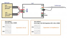
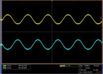
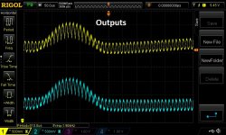
As far as the balance adjustment goes... (In the scope plots yellow is the + in or out, blue is the -).
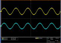
Normally, the inputs are in opposite phases (first scope image) as is the output (second scope image).
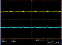
If you apply an in phase (common mode) signal to both the + and - inputs (third scope image) then the inputs will subtract. The output should be near nothing (fourth scope image), both differentially, and also on each of the + and - outputs as referenced to ground.
Measuring the balanced audio output on the analyzer, with a normal balanced 1V input, I measure 4.2V out; with common-mode (+ and - get the same signal) input, the balanced output measures about 4mV. Not perfect cancellation, but -60dB...
As for the balance pot R5: it just slightly attenuates one side vs. the other, to let you null the common mode gain to accommodate slight differences in gain from one half of the nutube to the other. So you adjust it to get a minimum differential signal at the output.
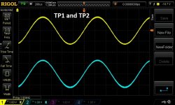
If there is no cancellation - if applying a common mode input gives you large output - then there must be something wrong with one side of the amp or the other. If you have an oscilloscope you can trace the signal. The two grids (TP1 and TP2) should show signals that look identical (though the DC voltage may be a little different). If not, there is a problem upstream in the buffers (Q1 & Q2).
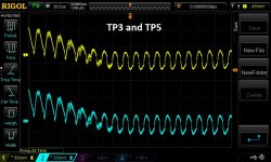
The two plates of the nutube (TP3 and TP5) should show very little movement, as the CCS should force balance between the two halves. If not, then the CCS may be messed up.
Hopefully that helps a little?
Pete
On the plate voltage... the exact voltage isn't all that important. On most nutubes with 221k plate resistors, you may hit the limit of the bias pots before getting to 5.4V. 5v or 6V is fine. You should adjust to get the two voltages close to each other, assuming you want minimum distortion, especially minimal 2nd harmonic. They do interact, since the CCS in the tail means that if you raise the current through one half, you will lower it in the other.
If you want to intentionally add 2nd harmonic, then you can skew the two a bit.
As far as the balance adjustment goes... (In the scope plots yellow is the + in or out, blue is the -).
Normally, the inputs are in opposite phases (first scope image) as is the output (second scope image).
If you apply an in phase (common mode) signal to both the + and - inputs (third scope image) then the inputs will subtract. The output should be near nothing (fourth scope image), both differentially, and also on each of the + and - outputs as referenced to ground.
Measuring the balanced audio output on the analyzer, with a normal balanced 1V input, I measure 4.2V out; with common-mode (+ and - get the same signal) input, the balanced output measures about 4mV. Not perfect cancellation, but -60dB...
As for the balance pot R5: it just slightly attenuates one side vs. the other, to let you null the common mode gain to accommodate slight differences in gain from one half of the nutube to the other. So you adjust it to get a minimum differential signal at the output.
If there is no cancellation - if applying a common mode input gives you large output - then there must be something wrong with one side of the amp or the other. If you have an oscilloscope you can trace the signal. The two grids (TP1 and TP2) should show signals that look identical (though the DC voltage may be a little different). If not, there is a problem upstream in the buffers (Q1 & Q2).
The two plates of the nutube (TP3 and TP5) should show very little movement, as the CCS should force balance between the two halves. If not, then the CCS may be messed up.
Hopefully that helps a little?
Pete
Attachments
OK, that was easy. I got both plates to 6.05 on one board and 6.07 on the other. No experience working with CCS. The only tube I’ve done is the Korg B1, which my wife stole for her studio setup after hearing it with our ACA monoblocks.
I’m converting an older design, Pass balanced Zen preamp, to Pete’s NuTube circuit. I figured as long as I had all that wiring done in a chassis that accommodated his boards and PS, I’d take advantage of it. Hope these NuTubes are as non-microphonic as the one in the B1K.
Thanks again, Pete.
I’m converting an older design, Pass balanced Zen preamp, to Pete’s NuTube circuit. I figured as long as I had all that wiring done in a chassis that accommodated his boards and PS, I’d take advantage of it. Hope these NuTubes are as non-microphonic as the one in the B1K.
Thanks again, Pete.
Well, I tested one board for all points today (1 hour warm up time):
TP3 = 5.5151VDC
TP5 = 5.5454VDC
TP1 = -10.6915
TP2 = -11.3685
TP4 = -13.067
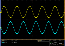
I attached scope images for signal tracing. TP1 and TP2 are correct. TP3 and TP5 as well as outputs are bad.
So, it seems that I have issue in CCS. Pete, can you please guide me for its troubleshooting?
TP3 = 5.5151VDC
TP5 = 5.5454VDC
TP1 = -10.6915
TP2 = -11.3685
TP4 = -13.067
I attached scope images for signal tracing. TP1 and TP2 are correct. TP3 and TP5 as well as outputs are bad.
So, it seems that I have issue in CCS. Pete, can you please guide me for its troubleshooting?
Attachments
Last edited:
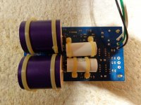
The only difference I see on my board vs. board image attached to product site is polarity for L1. I think such coils have no polarity and it is doesn't mater orientation. I also see on that image that U2 has reversed mark on silkscreen vs, mine, but device installed same as mine when my silkscreen is correlated to device orientation. Please correct me if I'm wrong.
Hi guys -
On the plate voltage... the exact voltage isn't all that important. On most nutubes with 221k plate resistors, you may hit the limit of the bias pots before getting to 5.4V. 5v or 6V is fine. You should adjust to get the two voltages close to each other, assuming you want minimum distortion, especially minimal 2nd harmonic. They do interact, since the CCS in the tail means that if you raise the current through one half, you will lower it in the other.
Hi Pete,
I have found that obtaining minimal H2 in the recommended range is easy, however H3 is high. Once H2 is then increased one can get the cascading waterfall distortion pattern you show.
To minimize both H2 and H3 requires quite a bit of difference in TP3 and TP5 readings but then I can get the distortion pattern I have shown in post #1which is a very pure H2. The cost is that CMRR suffers, since I can only get a under 30db reduction unlike the around 60db you mention. Sounds great for classical. Any concerns with this approach?
Thanks. nash
Well, I tested one board for all points today (1 hour warm up time):
TP3 = 5.5151VDC
TP5 = 5.5454VDC
TP1 = -10.6915
TP2 = -11.3685
TP4 = -13.067
I attached scope images for signal tracing. TP1 and TP2 are correct. TP3 and TP5 as well as outputs are bad.
So, it seems that I have issue in CCS. Pete, can you please guide me for its troubleshooting?
Actually I think this is fine. The high frequency stuff you see is being coupled from the DC/DC converter. If you ignore that, the differential output is very low and looks a lot like my waveforms. Note also that the HF noise is common mode, so it would be cancelled if the output is connected to something with a differential input. Plus it looks like it is above the audio band, maybe 50kHz?
Are you sure L1/L2/L3 are correct (330uH)? The polarity shouldn't matter, though it can have a small impact with regard to coupling. Ideally the start of the winding (buried inside the coil) is connected to the DCDC converter. But to be honest I paid no attention to that when I assembled the prototype.
I did see some noise from the DCDC converter in mine, though the level is much lower. You can see some "fuzzyness" on my scope plots.
It may make a difference where your scope probes are grounded. I grounded them to the output side ground. If you use the power supply ground it ight look worse.
You might want to poke around with no input signal (connect both + and - inputs to ground at the input connection) to see where you see the HF noise.
You can also experiment with trying to shield the DCDC converter itself. A bit of copper or aluminum foil around it? Be careful not to short anything, though.
Pete
No change to noise level during my experiments. Aluminum foil on DC to DC also didn’t change it.
Should I try higher inductance coils, and let’s say to double it? Also, my U4 has no sink yet and it is hot. It might be noise.. Board is not in grounded box and also it might picking up some RF... This ripples are in 100mv RMS window.
Should I try higher inductance coils, and let’s say to double it? Also, my U4 has no sink yet and it is hot. It might be noise.. Board is not in grounded box and also it might picking up some RF... This ripples are in 100mv RMS window.
No change to noise level during my experiments. Aluminum foil on DC to DC also didn’t change it.
Should I try higher inductance coils, and let’s say to double it? Also, my U4 has no sink yet and it is hot. It might be noise.. Board is not in grounded box and also it might picking up some RF... This ripples are in 100mv RMS window.
When I experimented with this, I found that changing the filters didn't make a lot of difference. It seemed like most of the noise was radiated, not conducted. The thing that made the most difference was physically relocating the converter away from the rest of the circuit.
I also tried several different converters. The one I settled on was this:
https://www.mouser.com/ProductDetail/XP-Power/IE0505S/?qs=w/v1CP2dgqoXUua2Bslg5g==
I think it is a little better than the one I originally had on the BOM.
A metal chassis may help.
The reg does run hot, though within its limits. Many people shoehorn a small heatsink in to cool it.
Pete
- Home
- Source & Line
- Analog Line Level
- Building the Pete Millett Korg Nutube Balanced Preamp