Would the Linear Audio silent switchers be good fit for this pre? Curious.
I would think so...
Pete
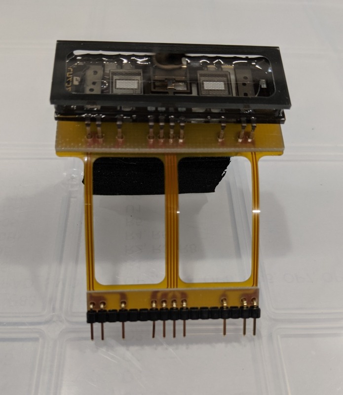
I came up with a way to decouple the nutube from the PCB to minimize the microphonics. It fits into the same spot as the tube.
I have to warn you, it's not easy to remove a nutube that's already soldered in, though...
Pete

Cool. And I see it in your eBay store. Yes, the only drag for already built circuits is the difficulty of unsoldering the NuTube. thanks.
Last edited:
Very nice idea.
BTW, I removed tubes several times during my assembly without any issues with my ZD985.
I personally do not have any microphonic effect, but that is question of luck with some tubes and chassis related position.

BTW, I removed tubes several times during my assembly without any issues with my ZD985.
I personally do not have any microphonic effect, but that is question of luck with some tubes and chassis related position.
Hi Alex,
While examining your build pics I notice you do not have standard resistors in R25, 26, 28 & 29. What are they? Their installation also looks interesting. How is the preamp performing after all this time?
While examining your build pics I notice you do not have standard resistors in R25, 26, 28 & 29. What are they? Their installation also looks interesting. How is the preamp performing after all this time?
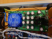
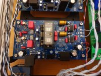
Hi organics1, are you asking about these four squre resistors (in attached image)? Ha, I used what I had in my home storege and these resistors are Dale RNC90Y (1k, 0.005%, 2 PPM). Definately overkill, but I just had these in hands. Nothing specific. I like that amp a lot and use it almost daily (luckaly, I'm still working from home). Nice reach sound and no issues to run it with my heavy for load Audeze LCD-4.Hi Alex,
While examining your build pics I notice you do not have standard resistors in R25, 26, 28 & 29. What are they? Their installation also looks interesting. How is the preamp performing after all this time?
Attachments
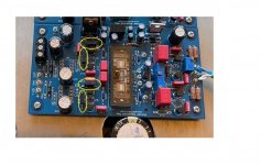
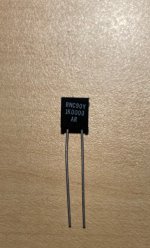
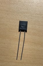
Alex,Hi organics1, are you asking about these four squre resistors (in attached image)? Ha, I used what I had in my home storege and these resistors are Dale RNC90Y (1k, 0.005%, 2 PPM). Definately overkill, but I just had these in hands. Nothing specific. I like that amp a lot and use it almost daily (luckaly, I'm still working from home). Nice reach sound and no issues to run it with my heavy for load Audeze LCD-4.
Sorry about taking so long to reply. It's called spacing out.
Yeah, some SERIOUS overkill! But that never stopped me from giving it a try. I figure since most of what I'll be using are premium parts I might as well extend that through as much of the chain as possible. I recently got in a small batch of Vishay trimpots from Texas Components, and I noticed they also have the same resistors you're using. Will buy some, though in a bit less expensive tolerance range than you've got.🙂
Also, since the resistor lead spacing is 5mm+ and the pcb spacing is 10mm, what scheme did you use for attaching them?
THANX
Good luck with your build. Once again, in my case and based on my opinion, it is very good amp.Alex,
Sorry about taking so long to reply. It's called spacing out.
Yeah, some SERIOUS overkill! But that never stopped me from giving it a try. I figure since most of what I'll be using are premium parts I might as well extend that through as much of the chain as possible. I recently got in a small batch of Vishay trimpots from Texas Components, and I noticed they also have the same resistors you're using. Will buy some, though in a bit less expensive tolerance range than you've got.🙂
Also, since the resistor lead spacing is 5mm+ and the pcb spacing is 10mm, what scheme did you use for attaching them?
THANX
I usually buy components when I don’t have any in my storage. and I always use same of higher spec on parts that I have in my garage. Same was for these resisters.I got them by weight from local junkyard many years ago. As you can imagine, I would not pay $25 for each resistor a specially for resistors in such circuit position. 🙂.
BTW, I did not use nothing fancy to installed these. I just bended long legs and soldered these in.
Hello everyone!
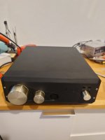
After working on and off on my amp and the case for a few years its finally finished. I wanna thank this thread and especially Mr. Millett and Nash for answering a bunch of my (quite basic) questions and helping me get this finished and I gotta say: I’m quite content and I love seeing the tubes glow ^^
However: When listening with it I have a sort of white noise on both channels, which sets in after a few seconds after turning the amp on and it’s very prominent: I can still listen to music but everything quiet is almost drowned by the noise.
It’s independent of the input, the position of my volume-potentiometer, the signal-grounding (connected to the mains-ground or separated), the shielding of the case, the shielding of the PSU, …
I have not found a way to influence it in any way.
But I have a suspicion: my power supply shows some behavior I can’t judge jet:
Even when turned off it still supplies
It's the balanced power supply by Mr. Millett for his LR-Phono-Preamp (http://pmillett.com/LR_phono.html) and I followed the schematic / BOM for the 230V here in Germany.
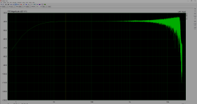
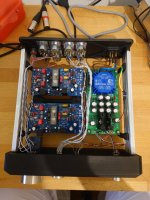
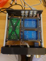
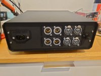
Attached are some pictures of my Amp and some Measurements in Arta using my Focusrite Solo and my Geshelli DAC. I tried replicating your settings here in the thread using my left channel as an example.
I really hope I just made an obvious mistake and you guys can help me one last time with my amp as I really loved working on this project.
This is my first electronics-project that went beyond just swapping parts or following direct instructions.
I thought it was fitting to post this here, but I can open a new thread if it would be better.
Some context for the construction and some of the visible strange choices on my boards:
If I missed to mention anything important or you need some more measurements/pictures, I'd be happy to supply them.
Thanks again and cheers!
Michel
After working on and off on my amp and the case for a few years its finally finished. I wanna thank this thread and especially Mr. Millett and Nash for answering a bunch of my (quite basic) questions and helping me get this finished and I gotta say: I’m quite content and I love seeing the tubes glow ^^
However: When listening with it I have a sort of white noise on both channels, which sets in after a few seconds after turning the amp on and it’s very prominent: I can still listen to music but everything quiet is almost drowned by the noise.
It’s independent of the input, the position of my volume-potentiometer, the signal-grounding (connected to the mains-ground or separated), the shielding of the case, the shielding of the PSU, …
I have not found a way to influence it in any way.
But I have a suspicion: my power supply shows some behavior I can’t judge jet:
Even when turned off it still supplies
-0,496V on the positive rail and
-0,517V on the negative rail.
When turned on it supplies+15,83V on the positive rail
-14,89V on the negative rail.
These values are measured after having the amp connected to power for a good few minutes but turned off and after leaving it turned on for half an hour respectively.It's the balanced power supply by Mr. Millett for his LR-Phono-Preamp (http://pmillett.com/LR_phono.html) and I followed the schematic / BOM for the 230V here in Germany.
Attached are some pictures of my Amp and some Measurements in Arta using my Focusrite Solo and my Geshelli DAC. I tried replicating your settings here in the thread using my left channel as an example.
I really hope I just made an obvious mistake and you guys can help me one last time with my amp as I really loved working on this project.
This is my first electronics-project that went beyond just swapping parts or following direct instructions.
I thought it was fitting to post this here, but I can open a new thread if it would be better.
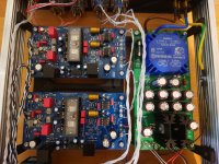
Some context for the construction and some of the visible strange choices on my boards:
- The Heatsink of U1 is admittedly quite close to R15, but I took care to isolate it electrically with Kapton.
- C23 and C24 are mounted like this because I played with the idea to use bigger Opamps down the line. I could easily reverse this if it’s a probable source of the problem.
- I socketed the tubes so that I can change them out a few years down the line. The connections should be free of resistance.
- Some of the soldering joints don’t look great admittedly as they are a few years old by now from a time when I made my first steps with leadless solder with silver. From what I and my Multimeter can tell the connection should be solid though.
- I took care to avoid ground-loops. Thus the ground cumulates in the power supply so to speak and the Pin 1 of the XLRs all connect to the case (which is in large parts 3d-printed, but I coated the inside of the parts with graphite-based shielding (conductive) paint).
- I used NKK MRA403 for switching the in- and outputs and an Alps RK27-pot for the volume before the input.
- I used the better DC-DC-Couplers recommended my Mr. Millett on the first page here instead of the ones on the BOM.
- I got the tubes measured in at ~6,45V. (TP3 & TP5) (not final, but at least matched).
If I missed to mention anything important or you need some more measurements/pictures, I'd be happy to supply them.
Thanks again and cheers!
Michel
Attachments

- Home
- Source & Line
- Analog Line Level
- Building the Pete Millett Korg Nutube Balanced Preamp