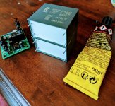
The small tube sockets are off-centered in their cutouts. Will the tube fit in there without colliding with the chassis?Not a lot of progress. I cut into my right hand thumb (I'm righthanded) with an angle grinder. Nothing serious...but it happened on the top of my thumb very sensitive. Don't ask me how because I don't know. It's all a blur. Bought my self cut resistant gloves the same day.View attachment 1268041
If you look at image #59 earlier in this post, the small tubes look off-centered while the large tubes appear to be on-center. Wouldn't all the sockets show a similar parallax effect with respect to their holes?
Somehow I never get it right some way to go with accuracy of drilling...but they will all fit without touching the chassis.

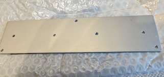
I never assume my material is the size it is supposed to be. I measure what I receive. For instance this is for a new project. Rectifier subchassis. I measure where I want stuff. Make a guide hole.always start your layouts from the same corner, never assume your material is the size its supposed to be and measure in from each side.
And use that as a template to drill into the main chassis. I.e. use it to mark where I should drill. Then punch it with the dot punch. Then drill.
Attachments
Last edited:
You could try connecting the lower side of the OPT to the top of the cathode resistors and the cap. Shortens the audio signal loop and removes the cathode bias parts from the signal path. It’s how I have mine.
I was wondering about that. Will try it this way and then the so called ultrapath way. Did you find it significantly better or just a tad better?
I didn't try it both ways, sorry. Having read over the years that connecting between plate and cathode was an improvement I just did it that way. The only comparative measurements I made were between this amp with the parafeed output and a version of it with a series feed output. The parafeed showed about 0.5% lower THD at 1kHz and 1W. I assumed, don't know for certain, that this was at least partly the result of the shorter and more direct signal path in the output circuit. Both amps had a similar high frequency response but the parafeed had a lower bass rolloff measured at 1W. The HF was -3dB at about 65kHz. The parafeed had a bass -3dB about 15Hz. Flat in between. It's funny that both versions had similar HF behavior but the series feed sound like it had more treble but to me it seemed sharper where the parafeed has a smoother less distorted character to my ear.
To try out an SE design, I have taken a push-pull transformer and placed B+ voltage at the center-tap of its primary. 1/2 of the winding went to the tube's plate, and the other half went to a constant current source set to the same current as the tube draws. That arrangement canceled out the magnetic field in the transformer's core, and since the constant current source has a load impedance in the megohms, it did not load down the tube. This eliminated the capacitor and the choke in the original design. That arrangement also allowed for the use of a smaller, non-gapped transformer.
egellings,
That is a good idea!
I might consider building that kind of topology.
For your SE design that used a push pull transformer:
What was your output tube type?
How many mA was your quiescent plate current?
What was the secondary plate to plate impedance?
What was the output transformer part number?
What was the CCS pass tube type?
Or what was the solid state CCS part number?
How did you get the CCS impedance to be Megohms, with current equal to the output tube's quiescent current?
What was the operating mode of the output tube, if it was not a triode?
For example, Pentode or Beam Power in native mode?
Triode wired Pentode orTriode wired Beam Power?
Tetrode wired Tetrode in native mode?
Thanks!
Using that kind of circuit:
A 10k plate to plate push pull transformer would provide a 2.5k Ohm load (plate to center tap), to a 2A3 (rp = 800 Ohms); thats good!
It is a Mean thing to say that Karl Friedrich Gauss was an Average man, who was Centered on his Gaussian Curve.
Last edited:
- Home
- Amplifiers
- Tubes / Valves
- Building parafeed EL84 DC 2A3 amp