Apologies .Typo error . Its 200ma in 20-0-20 Secondary and NOT Primary !Refer to the first post of this thread: Building Elvee's Circlophone: Documentation, Parts, Accessories, & beginner friendly
You can find the ideal values according to the supply voltage.
Note that this is not at all critical: a C built for +/-25V will accept between +/-15 and +/-40V
It is clearly abnormal, and I see two possible explanations:
-The circlophone actually consumes almost 50W, instead of 5W. This could be due to a dry joint, short, or misplaced component in the servo circuitry, making the amplifier to operate in ~class A.
In that case, heatsinks dimensioned for normal AB operation are going to become boiling hot after a few minutes of operation.
-The transformer has an excessive magnetizing current, because of poor quality iron, bad construction or inadequate primary voltage.
This is not a source of problem, unless the transformer itself becomes hot.
To determine whether the current is reactive or not, your friend should measure the active power consumption using a wattmeter rather than an ammeter.
Here is an example (there are many of them): Kill A Watt Meter - Electricity Usage Monitor | P3
If the (active) power consumption is <10W, everything is fine, it's just the transformer.
If it is larger, your friend should examine the C he built.
Without a wattmeter, he can also disconnect the DC supply from the C and check the current consumption: if it remains high, the transformer is the culprit
If it works in class A, he is certainly going to be delighted (until a meltdown occurs)
Emitter resistors are running cool.
Series mains 230V lamp was also off
Used V+V-(27+27-) and R21 (47k instead of 33k recommended in chart). Now the heatsink runs cooler and secondary trafo current is almost 200mA constant? What does R21 influence
It establishes the servo bias currents, and has a secondary influence on the quiescent current.
It is not at all critical, and if you prefer a slightly cooler C, you can increase it (within reason)
It is not at all critical, and if you prefer a slightly cooler C, you can increase it (within reason)
Can a 100k stereo log pot be used at the input or is there any other recommended value of a pot?
Thanks
Thanks
I recommend 4.7K log, 10K max.
Larger values are usable, but they are going to influence the THD
Larger values are usable, but they are going to influence the THD
One more build
Hi Elvee,
Thanks for your creation. I have built one channel on perf board, and it seems to perform just great, especially piano and vocals. The bass is quite good as well.
I used the prescribed components with TIP3055 as outputs. I used 200pF for C12 for now. My supply voltages turned out to be +- 27.8 V, so I added a trim pot (10K) to R21, to adjust the current through R21. The R21 current is 1.38 mA, and the current through R8 is around 230 mA. I kept the two zeners as 12V.
The heat sinks are barely warm, and less warm than the other class AB amps I have.
Now, on to the second channel...
There was some discussion on having hexfets for the output stage, and you had proposed a circuit with N-MOS outputs. I was wondering if we could use P-MOS devices, so I can just switch the outputs and reuse the existing PCB(perf boarded), without a major sex change operation. Ofcouse I can switch in the higher gate stopper resistors. I simulated the P-MOS version and it seemed to behave well. Are there any down sides in using the P-MOS output devices? This is just for my understanding, and apologies if this is a silly proposition.
Thanks again.
PMOS can work, and are theoretically the shortest path from a regular C to a MOS version, but unfortunately the technology of Si only allows second-best transistors in their P version: they use a larger die, have larger capacitances, higher Rdson, lower transconductance and they are more expensive (and rarer).
If none of this is an obstacle for you, PMOS are OK, otherwise use the sensible option adopted by other members: inverted circlophone, where all the polarities are reversed.
If none of this is an obstacle for you, PMOS are OK, otherwise use the sensible option adopted by other members: inverted circlophone, where all the polarities are reversed.
BTW, a specific High Power Circlophone thread has been launched here:
High-Power Circlophone
At the moment, it discusses theoretical options and problems and has not yet given birth to a practical project, but it will probably arrive soon, since member Minek seems determined to build one
High-Power Circlophone
At the moment, it discusses theoretical options and problems and has not yet given birth to a practical project, but it will probably arrive soon, since member Minek seems determined to build one
P-MOS lateral circlophone build
Hi Elvee,
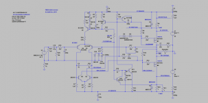
After completing the second channel of the BJT version, I went on to build a modular PCB, which can accomodate BJT, P-MOS Lateral, P-MOS Vertical output stages.
I built a P-MOS Lateral version first and it seems to work fine. I have attached the simulation circuit, and the computed values seem to match in reality. There is 1.48 mA through R21.
I have a question regarding the low current through R9 and subsequent low currents through Q5 and Q6. I was hoping for higher currents, so I can bias the mosfets a little higher. Is there cause for concern or do you think I should leave it as it is?
The sound is spectacular, with details in vocals I hadn't heard before.
I need to build the other channel before trying out the P-MOS Verticals (IRFP9140).
Thanks again for this wonderful and accomodating design.
Hi Elvee,
After completing the second channel of the BJT version, I went on to build a modular PCB, which can accomodate BJT, P-MOS Lateral, P-MOS Vertical output stages.
I built a P-MOS Lateral version first and it seems to work fine. I have attached the simulation circuit, and the computed values seem to match in reality. There is 1.48 mA through R21.
I have a question regarding the low current through R9 and subsequent low currents through Q5 and Q6. I was hoping for higher currents, so I can bias the mosfets a little higher. Is there cause for concern or do you think I should leave it as it is?
The sound is spectacular, with details in vocals I hadn't heard before.
I need to build the other channel before trying out the P-MOS Verticals (IRFP9140).
Thanks again for this wonderful and accomodating design.
Attachments
3mA through Q5 and Q6 is indeed a bit low.
Such a low current could have a negative impact on the slew-rate for example.
It is caused by the large (relatively) R9 R10 and small threshold voltage of the PMOS.
The solution is to reduce R9,10: this will force the servo to increase the current in Q5 and Q6.
A value of 68 or 56 ohm should be adequate.
200mA through the output seems right on target; if you want to increase it (I don't think it is necessary), you can decrease R21
I reduced R9, R10 to 68 and things look good now. There's around 12 - 13 mA through Q5, Q6. I also increased I(R21) to 1.52 mA. The outputs are running a little hotter now.
It sounds very good, and I will keep this configuration for testing. Now, on to the next channel.
Thanks and Happy Holidays!
It sounds very good, and I will keep this configuration for testing. Now, on to the next channel.
Thanks and Happy Holidays!
Auriga, have you managed to build HexFet version?Both channels of the P-MOS latfet version circlophone functioning nicely.
How did it go? Any changes vs LatFet version?
Hi Minek, I am yet to build the HexFet version. The two versions (BJT and LatFets) are working fine.
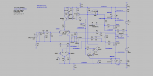
I made a quick LTSpice sim of circlophone with 50V rails,
and IRFP9240 outputs.
It seems to be ok.
asc file + models attached as zip file.
Elvee, do you think it looks OK?
I thinking about building it with IXTN40P50P outputs, and maybe
will try experiment with slightly higher rail voltages...
and IRFP9240 outputs.
It seems to be ok.
asc file + models attached as zip file.
Elvee, do you think it looks OK?
I thinking about building it with IXTN40P50P outputs, and maybe
will try experiment with slightly higher rail voltages...
Attachments
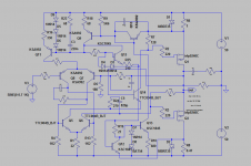

In both builds (BJT, LatFet), I noticed the two caps (C8, C9) got quite warm. I introduced this RC filter to isolate the two channels which share the single PS. See the circuit from post #457.
Any clues?
Any clues?
is polarity on these caps correct?
the only case I'm aware of when electrolytic cap gets hot,
is when it's installed "backwards", and about to explode 🙂
Another possibility - there is significant AC current flowing through them.
Either from the psu, or perhaps from some kind of oscillation?
the only case I'm aware of when electrolytic cap gets hot,
is when it's installed "backwards", and about to explode 🙂
Another possibility - there is significant AC current flowing through them.
Either from the psu, or perhaps from some kind of oscillation?
Polarity, voltage, proximity with a heat-generating component.Any clues?
Heating caused by a high AC current is in principle a possibility but with such large caps, the current would need to be huge, and it would have effects elsewhere.
- Home
- Amplifiers
- Solid State
- Building Elvee's Circlophone: Documentation, Parts, Accessories, & beginner friendly