hi all,
All the Circlophone (Complementary Feedback Pair) PCB documents.
Final board revision.
enjoy!
hi,what scheme should i use?
thnaks
Where did you purchase TTC004B ?TTC004B and 2sc5171 seem very similar except the pinout is ECB vs BCE. Fortunately, flipping the 2s5171 180° is all that is required.
They seem to be out of stock everywhere...
Where did you purchase TTC004B ?
They seem to be out of stock everywhere...
I bought mine from Mouser last year. All the usual North American suppliers seem to be out of stock with long lead times. The same applies to many similar transistors also in TO-126 packages.
Where did you purchase TTC004B ?
They seem to be out of stock everywhere...
Just got some Toshiba VAS transistors TTC004B (Cob 12pF) from Japan.
If anybody needs them, let me know. Minimum order was 50 pcs..
Also a question - they are TO-126, all plastic, no metal pad for heatsinking.
Does it make sense to put them on the heatsink anyway?
You can, if your C version is high-voltage/high-power, but for "normal" situations the 1W~1.5W capability of the package alone is ample enough.Does it make sense to put them on the heatsink anyway?
I successfully used TTC004B as VAS transistors on my circlophone. I currently have only one channel working on a temporary heatsink. Testing so far has been rather minimal. Both channels will go into a permanent enclosure next month. PCB is my design: the only significant differences from most other circlophone PCBs are changing the VAS transistors to TO-126, and moving the KSA1220 drivers and MJL21194 outputs to better support mounting the PCB on the heatsink.
Thank you dear Frank ! Received the PCBs (by my nephew. Will reach me shortly) and the files. Thank you very much !
Did you complete the assembly and is the amp working normally ?
Thank you dear Frank ! Received the PCBs (by my nephew. Will reach me shortly) and the files. Thank you very much !
Did you complete the assembly and is the amp working normally ?
gannaji,
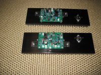
I completed this amplifier build about eight months ago and am very happy with the result. Speakers used with this amplifier vary but is currently is an Aplair 10m MLTL. Power supply is a Connex SMPS300RE +/- 35V with an ebay "2409-2" aluminum chassis.
Attached is a picture of the two boards mounted on their heatsinks. This arrangement allows for a more compact build and probably better heat dispersion than with boards designed to be mounted horizontally.
Attachments
Request help for Elvee
D4,D5 :Is it ok to use SR504 instead of MBR340
C4 : 25pf or 27pf . What type of capacitor is this ?
D4,D5 :Is it ok to use SR504 instead of MBR340
C4 : 25pf or 27pf . What type of capacitor is this ?
Request help for Elvee
D4,D5 :Is it ok to use SR504 instead of MBR340
C4 : 25pf or 27pf . What type of capacitor is this ?
I'm not Elvee, but I'm using SR504 and it works perfectly.
In perfect world, C4 should be mica capacitor. Mine is 27pF.
Any other alternatives to Mica ?I'm not Elvee, but I'm using SR504 and it works perfectly.
In perfect world, C4 should be mica capacitor. Mine is 27pF.
@nareshn,
a COB Ceramic KERKO schould also work there.
2x Keramik - Kondensator 27pF, 27pK COb ca.o8x2,5 RM5 (Kerko)Y501 | eBay
KERKO-500 27P: Keramik-Kondensator, 500V, 27P bei reichelt elektronik
Don't know about loosing some sound.
Try it out and if you find Mica's you can possibly change.
Good luck.
a COB Ceramic KERKO schould also work there.
2x Keramik - Kondensator 27pF, 27pK COb ca.o8x2,5 RM5 (Kerko)Y501 | eBay
KERKO-500 27P: Keramik-Kondensator, 500V, 27P bei reichelt elektronik
Don't know about loosing some sound.
Try it out and if you find Mica's you can possibly change.
Good luck.
Thank You@nareshn,
a COB Ceramic KERKO schould also work there.
2x Keramik - Kondensator 27pF, 27pK COb ca.o8x2,5 RM5 (Kerko)Y501 | eBay
KERKO-500 27P: Keramik-Kondensator, 500V, 27P bei reichelt elektronik
Don't know about loosing some sound.
Try it out and if you find Mica's you can possibly change.
Good luck.
I answered this question by PM, but for the benefit of the whole community, I shall restate it here:
The diodes are ideally any schottky in the (loose) 3A to 10A range, but fast Si diodes will also work, with a slight loss of output swing.
Even ordinary slow diodes are going to work, but if you test the amplifier with a full power >10kHz signal, the quiescent current will wander outside its normal bounds, but not in a catastrophic or even audible manner, because the power will be sufficient to mask any potential Xover artifact.
Anyway, schottky's are ubiquitous nowadays, so they shouldn't be a problem.
With C4's value, all the possible alternatives are suitable: MLCC COG, or any other tempco, idem for ordinary ceramic, mica, polystyrene, air, polypropylene or even vacuum: even if you tried to, you couldn't go wrong there, unless you try to make your own cap from orange peels, cotton cloth or similar improvised material.
Any other question useful to the community should be posted directly on the thread (main or build).
PM's should be used for private purposes only (personal information, payment details, etc)
Do BD140 and MJL21194 have to be mounted on same heatsink or seperate heatsinks.
Going by first few posts i infer both options are possible ( ie mount BD140 and MJL21194 on same heatsink or seperate heatsinks).Thanks.
Can folks provide guidance .Is this for +/-25V @4Ohms .
A colleague of mine has built one channel for me and reported 200mA on primary 20-0-20 transformer side !!
However the amp is working . He was delighted with what he heard.
Thank you Elvee !!!
A colleague of mine has built one channel for me and reported 200mA on primary 20-0-20 transformer side !!
However the amp is working . He was delighted with what he heard.
Thank you Elvee !!!
Last edited:
Refer to the first post of this thread: Building Elvee's Circlophone: Documentation, Parts, Accessories, & beginner friendlyCan folks provide guidance .Is this for +/-25V @4Ohms .
You can find the ideal values according to the supply voltage.
Note that this is not at all critical: a C built for +/-25V will accept between +/-15 and +/-40V
It is clearly abnormal, and I see two possible explanations:A colleague of mine has built one channel for me and reported 200mA on primary 20-0-20 transformer side !!
-The circlophone actually consumes almost 50W, instead of 5W. This could be due to a dry joint, short, or misplaced component in the servo circuitry, making the amplifier to operate in ~class A.
In that case, heatsinks dimensioned for normal AB operation are going to become boiling hot after a few minutes of operation.
-The transformer has an excessive magnetizing current, because of poor quality iron, bad construction or inadequate primary voltage.
This is not a source of problem, unless the transformer itself becomes hot.
To determine whether the current is reactive or not, your friend should measure the active power consumption using a wattmeter rather than an ammeter.
Here is an example (there are many of them): Kill A Watt Meter - Electricity Usage Monitor | P3
If the (active) power consumption is <10W, everything is fine, it's just the transformer.
If it is larger, your friend should examine the C he built.
Without a wattmeter, he can also disconnect the DC supply from the C and check the current consumption: if it remains high, the transformer is the culprit
If it works in class A, he is certainly going to be delighted (until a meltdown occurs)However the amp is working . He was delighted with what he heard.
- Home
- Amplifiers
- Solid State
- Building Elvee's Circlophone: Documentation, Parts, Accessories, & beginner friendly