
 )
)
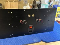
Sounds like your wife is just like mine - "oh no not another one of those big ugly black boxes". I offered to do the next one in silver, but that did not seem to garner any praise either. Oh well at least I tried!
To be fair, I did take over the dining room table as a staging zone. Hehehe!
That would not be allowed here, you must be a sweet talker Vunce and don't scratch the table.
You can buy them from Element 14 here in Australia.
Thanks, guys.
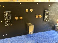
Lovely work as usual Vunce. What is the 'high voltage ' module please? Looks like an MJ design but don't remember seeing that one.
I would say that is the Soft Start pcb feeding mains to the transformer.
Vunce, Looking at the Wago terminals, I assume the splicing connectors (221-412 for the 2 way) are electrically connected across the 2 poles?
Also, for the mounting carrier (221-500), how many 2 way splicing connectors will it accommodate?
Keep up the great work, you are an inspiration around here.😉
Lovely work as usual Vunce. What is the 'high voltage ' module please? Looks like an MJ design but don't remember seeing that one.
https://www.diyaudio.com/community/...-pillow-sfp-ssr-soft-start-circuit-gb.350441/
I doubt that observation of bass without punch has anything to do with JFETs. It is rather the whole amplifier design. Bass definition could be affected by frequency response and damping factor. Loudspeaker excursion control in the LF range is more controlled by box design than by DF. There is also a counterintuitive effect that amplifier with a very low DF and certain loudspeaker boxes, could have more bass as LF driver is not well controlled.
Anyway, this amplifier has absolutely ridiculous DF of 1300 in the LF region. I had to arrange a special measurement setup to be able to precisely measure that.
Mind you, above DF of 200, any measurable effects, even with loudspeakers impedance dipping very low, are far beyond audibility.
Now, a short answer to your question. 🙂
Bass is very well defined. After moving test amplifier from improvised to final build, it was like subwoofer was added. 😀
Last edited:
Interesting project and I eagerly await others opinions.
Out of interest I just put the gerbers into JLCPCB. 10 boards are only a marginally more expensive than the minimum of 5.
Out of interest I just put the gerbers into JLCPCB. 10 boards are only a marginally more expensive than the minimum of 5.
Yes that is usually the case except for larger pcb's - however you might find the freight cost jumps a lot more, with double the weight.

Yes sorry I suppose I didn't word that very well.....there's the hefty engineering fee I guess for the 4 layer. 5 boards totalled £23 and 10 was £27. Shipping only a couple £ moreInteresting project and I eagerly await others opinions.
Out of interest I just put the gerbers into JLCPCB. 10 boards are only a marginally more expensive than the minimum of 5.
- Home
- Amplifiers
- Solid State
- Building an ultimate low power class A amplifier – my way