I think per tombo suggestion using 12VAC with an active rectifier I get around +/-17.65vdc unloaded. Active rectification usually gives around 1-1.5vdc more than conventional bridge rectifier as the losses are less and hence went with this rather than 15vac secondary toroidal.Thanks for that, so to aim at the 17.5 to 18VDC at the amp under load, it looks like the optimum AC secondary voltage is 14 to 15VAC (300VA should be more than big enough). Just as well you are using the prasi active rectifier CRC board, with normal diode bridge your DC volts would be a volt or so lower again. I am going for a 15VAC dual secondary transformer, and will add extra psu capacitance after the CRC board dual mono with 100,000uF per rail per channel - 44,000uF per rail on the CRC and an extra 56,000UF per rail chassis mount cap. Hopefully that will be beefy enough. My chassis will be bigger than yours shown in the photo. Will also run at 1.2 ADC bias current.
I will also be using a regulated supply, so need a few volts up my sleeve, will use the same CRC boards as you have.
If mentioned additional 56 mF capacitors are meant to be after the regulated PS, then they are with no function other than increasing weight.I will also be using a regulated supply
Voltage regulators keep output flat under any load change. Several mF at output is fine. I have 10 mF Kemet ALC10S at PS output.
With regulated PS first reservoir capacitor should be big as it gets. With unregulated PS, I would use big capacitors for booth positions or bigger one at the output.
I am thinking about using this amp for my super low-efficient headphones. They are 60 Ohm impedance (flat across the audio spectrum). Efficiency is only 83 dB-SPL @ 1 Vrms. The target for the output voltage and current (peak values) would be +/- 23 V and +/- 0.4 A. Yes, that's a lot for headphones, but that's what I'd want and need. So, I am wondering if / how this could be achieved with this amp design. My guesstimate for the biasing of the output stage would need about +/- 25 VDC rails, with a bias current of 0.4 A. I guess that would be relatively straight forward to implement, except...
...what would be the best way out? Would I need a different opamp that can swing more voltage?
+/- 17 V is target supply voltage. It can't be higher than some +/- 18.5 V due the opamp in front.
...what would be the best way out? Would I need a different opamp that can swing more voltage?
what would be the best way out? Would I need a different opamp that can swing more voltage?
For such high swing, only solution would be a different opamp as is OPA551/552 but performance would be nowhere near in all departments. Opamp supply can be +/- 18 V and amplifier supply +/- 20 V. That would provide max. +/- 17 V peak output. Unfortunately, this amplifier is not a swiss knife. 🙂
However, clean 10 V rms, which this amplifer can provide, is 103 dB at your eardrums.
Bias would be enough at 0.2 A for remaining in class A up to 0.4 A peak.
Have you considered this amplifier: https://www.diyaudio.com/community/threads/small-class-a-amplifier-with-thd-below-0-0001.385676/


Happy New Year tombo
I don't know how you dreamt this one up 😉
but this diamond configured output is really intriguing...
Congrats on this fine design.
Anyway, for now happy new year
rebone
I don't know how you dreamt this one up 😉
but this diamond configured output is really intriguing...
Congrats on this fine design.
Anyway, for now happy new year
rebone
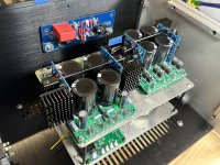
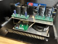
Made some progress on Bliss this relaxing first day of the new year.
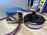
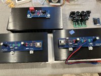
Worked on the PSU mechanicals and fitment today. She’s a double decker!
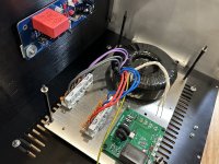
I like to use WAGO connectors in order to made changes/modification easier.
Rear panel layout and machining is next up….
Happy New Year!
Worked on the PSU mechanicals and fitment today. She’s a double decker!
I like to use WAGO connectors in order to made changes/modification easier.
Rear panel layout and machining is next up….
Happy New Year!
Attachments
Being in construction, A fine home is built on a solid foundation 
That will be one Big Little Amplifier. 🙂
Happy New Year to all and may your DIY projects be successful.
Happy New Year to all and may your DIY projects be successful.
I like to use WAGO connectors in order to made changes/modification easier.
What are 'WAGO' connectors, V?
Happy New Year!
And to you, too. 👍
The plan for this chassis is to share time between two amplifiers. (F6 Diamond and Bliss)
Swapping heatsinks and power transformer then adjusting R21 modules for proper output voltage is all that's needed to pull this off. The WAGO 221 connectors will make swapping the Toroidy's super easy and convenient.
Swapping heatsinks and power transformer then adjusting R21 modules for proper output voltage is all that's needed to pull this off. The WAGO 221 connectors will make swapping the Toroidy's super easy and convenient.
Attachments
- Home
- Amplifiers
- Solid State
- Building an ultimate low power class A amplifier – my way