I think that is sound advice.
The pots are subjected to 0.4W so are very close to their design limit.
I'll swap them out for some 2W pots.
The pots are subjected to 0.4W so are very close to their design limit.
I'll swap them out for some 2W pots.
I've repaired the PCB, new R22 & R24 and cleaned up the soot from those blown components. Insulation and continuity tests all are OK around the valves.
I've not tried applying 100V across the bias pots but their resistances all seem OK and vary as they sweep.
I can only assume that the travel in the pots allows each valve to enter a dangerous conductive / destructive state.
However, I was measuring the cathode current across the cathode resistor and couldn't see anything going haywire until the valve started arcing and went blue.
I've now got some 100mA meters to put in series with the OPT for testing.
Do put in the 470k from the wiper to the negative rail as suggested in case the wiper comes off. Also check that with no output valves in the grid does go over the correct range.
That schematic allows the grid voltage to go right up to 0V at one end of the pot causing destruction. That's really crap. The pots need a resistor in series with the ground end to stop say going less than -30V. I think you have a very good case on ebay for claiming for new valves as the design is 'not fit for purpose'.
Do add the ground resistors before you put the valves in again that's really poor before you pop another set.
Last edited:
R26 is in series with the grid bias pots.
It limits the wiper voltage (with 22K pots) between 0 and -56V.
One limit of this destroys the EL34, I'm guessing -56V.
It limits the wiper voltage (with 22K pots) between 0 and -56V.
One limit of this destroys the EL34, I'm guessing -56V.
Last edited:
Other way round its the 0V that destroys the devices. Have a read on wiki, they are similar to jfets.
What "SAFE" range should I limit the bias voltage within ?
I'm guessing that -39V should be the aim point.
So maybe -30 to -50V ??
I'm guessing that -39V should be the aim point.
So maybe -30 to -50V ??
Last edited:
You can go upto -100v but beyond -60 is of no use. So Yes say -30-50V. I would guess operating about -37v.
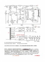
Anyone joining this conversation late, we are building this E-Bay version of the Williamson 5-20.
Williamson push-pull Amplifier circuit board For 12AX7/12AU7/EL34/KT88/6P3/6L6 | eBay
The PCB is well made but has serious design issues around the bias pots.
Williamson push-pull Amplifier circuit board For 12AX7/12AU7/EL34/KT88/6P3/6L6 | eBay
The PCB is well made but has serious design issues around the bias pots.
Attachments
Last edited:
I have a suggestion, if you don't mind. Why not convert it to a real Williamson? Skip the fixed bias, it really doesn't gain you anything here. Off-board the classic Williamson cathode resistor and balance pot, change a few values on the board, and get the real deal. Cathode-bias with a common cathode resistor is part of the Williamson magic. What output transformers are you using?
I was looking at these boards and thinking that with a few mods they'd be great for a "production" run of classic Williamsons.
ETA: I see you're using 6.6K transformers. You really want cathode bias with those anyway. Take a look at the first ultralinear design, it would work very well here, provided your OPT's have sufficient bandwidth.
https://dalmura.com.au/static/Radio-News-1953-02.pdf
,,,and a to be accurate, Williamson is not a "5-20." That's a completely different topology developed by Mullard.
Last edited:
yep a resistor in series with the trimmer to ground will stop the popping, you can test with the EL34's missing. Cathode bias is safer and is less prone to drift, but will give you a little less output power, and gives you crossover distortion when driven hard. The choice of bias does not affect the OPT. I would make the minimum changes to make it work.
Last edited:
One of the big draws of the Williamson (topology) is that it can have a lot of loop gain, and therefore distortion correction. This one is sort of stripped down, with both front end stages implemented with low mu triodes, and the outputs triode strapped. This doesn’t have anywhere near as much loop gain as you *could* have with the sane number of valves. Less loop gain means less stability problems than you typically run into. Why did they do it this way? So that newbies who don’t know any better won’t end up making an oscillator. So they got this right for making a “foolproof” kit - unfortunately just a couple extra three cent resistors would have made the bias circuit more fail safe and idiot proof. Cathode bias would have made it easier still, but we’re already crippled for power running triode into a high Z load, and I doubt there is enough headroom loop gain wise to put up with increased “crossover distortion when driven hard”. As the design is, it relies on having good open loop linearity which you don’t want to give up. It will probably *sound* pretty nice, once it is finally up and running.
Umm, the 12AU7 gain and plate resistance is about the same as a 6SN7. And the KT66 triode strapped is pretty similar to the EL34 triode strapped. So I think your assessment has no basis.
That said, there are differences, and it is up to the user to choose an output transformer, so like all other clones - caveat emptor on HF and LF stability.
That said, there are differences, and it is up to the user to choose an output transformer, so like all other clones - caveat emptor on HF and LF stability.
One of the big draws of the Williamson (topology) is that it can have a lot of loop gain, and therefore distortion correction. This one is sort of stripped down, with both front end stages implemented with low mu triodes, and the outputs triode strapped. This doesn’t have anywhere near as much loop gain as you *could* have with the sane number of valves. Less loop gain means less stability problems than you typically run into. Why did they do it this way? So that newbies who don’t know any better won’t end up making an oscillator. So they got this right for making a “foolproof” kit - unfortunately just a couple extra three cent resistors would have made the bias circuit more fail safe and idiot proof. Cathode bias would have made it easier still, but we’re already crippled for power running triode into a high Z load, and I doubt there is enough headroom loop gain wise to put up with increased “crossover distortion when driven hard”. As the design is, it relies on having good open loop linearity which you don’t want to give up. It will probably *sound* pretty nice, once it is finally up and running.
As Tim points out, plenty of Williamsons were made with 12AU7s instead of 6SN7s, the difference is very slight. The Heathkit W5 used them, along with KT66s, and a DIYer friend of mine uses the W5 circuit to very good effect in his own Williamson amps. Open-loop gain is not a problem here. Otherwise I agree that the board has some issues, but could be easily corrected.
The problem with *any* Williamson amp employing the correct amount of feedback is the danger of oscillation, and the only way to ensure against that is to be able to 'scope the amp and fine tune (in this case) R10, C3 and R22, and add a phase lead cap across R22 if needed. C3 should probably be increased to 200pF for starters, that's the standard Williamson shelf network.
But maybe it works fine as is. I don't know what output transformer the designer intended here, apart from a 5K primary. I think the 1650H would probably do the job and using the ultralinear taps you'd have a nice 22 wpc amp.
I don't want to play with the board too much as I might have to return it if it's a failure. I've already replaced the two burnt resistors, scrubbed off the soot and re-lacquered the PCB.
I can see the that major problem is that the bias pots can (and did) adjust the EL34s into destruct territory.
I'm adding 4K7 between the pots and 0V to limit their adjustment range.
I've got 4 x brand new EL34s. I'm just waiting on the 2W pots.
I have an oscilloscope if necessary, but during the brief period that I had it running, other than humming, it wasn't oscillating.
Initially I was measuring the Iq across the cathode resistors. Now I have 200mA meters in the OPT legs.
Last edited:
Okay, well I hope the bias pot fix takes care of things. I'll just note that oscillation can take place at very high frequencies if the output transformer can't handle the amount of feedback apllied. It would be a good idea, when you get it up[ and running, to take a look at a 10kHz square wavwe and see if there's excessive overshoot or rining.
- Home
- Amplifiers
- Tubes / Valves
- Building a Williamson EL34 amplifier