Try moving the input screened cables away from the toroid. Please to see they run together to prevent a differential loop.
A few ways to include/exclude your hum/noise. For example,
- battery power the heaters.
- temporary short across the pcb signal input terminals
- pull out V2
- do all of the above with and without GNFB connected
- measure what your GNFB level in dB is (ie. if you are only applying 6dB feedback, then increasing that to 12dB may drop your hum by 6dB - but you then should preferably measure your stability margins)
- how well did you balance the EL34 cathode currents? (and btw how do you access the bias trimpots?)
- what are the dc circuit voltages at idle (eg. mark up the schematic)?
But you should aim to use a meter or hum level benchmark measuring of some sort to determine the change. The better method imho is to prepare soundcard/laptop/spectrum analyser type measurement tool, so the hum frequencies and their magnitudes can be identified.
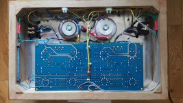
Are the brown wires going to the pcb (near the input signal wires) the output wires used for feedback? As they have a relatively high signal level on them, it may be preferable to distance them as much as possible from the input signal wiring, and to separately shield them on their way back to the pcb (to avoid cross-channel coupling and stray pickup). Is each output grounded separately at the pcb common gnd point? It may be better to ground each speaker output directly to the ground end of their respective R2, although that may depend on pcb layout as the speaker ground would carry parasitic capacitance current from the output stage main signal loop.
What are the two power transformers specifically for? Do they have a large steel washer between the core and (aluminium ?) chassis ?
- battery power the heaters.
- temporary short across the pcb signal input terminals
- pull out V2
- do all of the above with and without GNFB connected
- measure what your GNFB level in dB is (ie. if you are only applying 6dB feedback, then increasing that to 12dB may drop your hum by 6dB - but you then should preferably measure your stability margins)
- how well did you balance the EL34 cathode currents? (and btw how do you access the bias trimpots?)
- what are the dc circuit voltages at idle (eg. mark up the schematic)?
But you should aim to use a meter or hum level benchmark measuring of some sort to determine the change. The better method imho is to prepare soundcard/laptop/spectrum analyser type measurement tool, so the hum frequencies and their magnitudes can be identified.
Are the brown wires going to the pcb (near the input signal wires) the output wires used for feedback? As they have a relatively high signal level on them, it may be preferable to distance them as much as possible from the input signal wiring, and to separately shield them on their way back to the pcb (to avoid cross-channel coupling and stray pickup). Is each output grounded separately at the pcb common gnd point? It may be better to ground each speaker output directly to the ground end of their respective R2, although that may depend on pcb layout as the speaker ground would carry parasitic capacitance current from the output stage main signal loop.
What are the two power transformers specifically for? Do they have a large steel washer between the core and (aluminium ?) chassis ?
Last edited:
TROBBINS, the bias pots are remote and on top of the chassis so easy to reach.
The bias is 40mA / valve as close to zero tolerance as I can see on the meters.
The bias is 40mA / valve as close to zero tolerance as I can see on the meters.
The green loops at top left and right are the unused taps from the OPTs.
The black boxes are the breakout boxes for connecting the mA meters for bias adjustment.
The black boxes are the breakout boxes for connecting the mA meters for bias adjustment.
You can clearly see the central 0V point on the PCB. The only connections are the 0V returns from the OPTs and the GND lift to Earth.
It is quiet with everything connected.
The humming is only apparent when the pre-amp is switched on.
We are talking about a miniscule hum that is barely audible.
The humming is only apparent when the pre-amp is switched on.
We are talking about a miniscule hum that is barely audible.
Maybe the bass is better in the new amp, or its creating a hum loop into your pre-amp. Is the preamp a diy design or bought in? Is the signal grounded to the mains earth there?
The pre-amp is an Aleph P1.7 (DIY).
The pre-amp is a balanced unit, the Alephs use balanced inputs.
I can't recall if it has a ground loop breaker or not, I'll check later.
The Williamson has an unbalanced input.
The pre-amp is a balanced unit, the Alephs use balanced inputs.
I can't recall if it has a ground loop breaker or not, I'll check later.
The Williamson has an unbalanced input.
Last edited:
I gave up on unbalanced grounded signal cables years ago, on ANY audio equipment t which uses a three prong plug. Not everything has truly balanced inputs but every piece has either differential or transformer isolated inputs. I will never run the audio signal return though the shield, period. Everything that is intended to drive something with a three prong plug has active balanced outputs, except for the few lower end Pro pieces that only have impedance balanced and I haven’t torn into them yet. It’s not worth it to spend a bunch of time building something nice, then fight with a ground loop. Design the solution in and be done with it.
If it’s silent with nothing plugged in the amp, then hums as soon as another device is connected it’s a ground loop. I’ve even had ground loops that don’t make physical sense - With no obvious path - and putting in the damn transformer fixed them every time. So did plugging it into an extension cord with a missing 3rd prong (so I know it was a ground loop) but if you do that DJing a school dance and someone finds out you never work again. Now I simply won’t give a piece of equipment the opportunity to annoy me.
If it’s silent with nothing plugged in the amp, then hums as soon as another device is connected it’s a ground loop. I’ve even had ground loops that don’t make physical sense - With no obvious path - and putting in the damn transformer fixed them every time. So did plugging it into an extension cord with a missing 3rd prong (so I know it was a ground loop) but if you do that DJing a school dance and someone finds out you never work again. Now I simply won’t give a piece of equipment the opportunity to annoy me.
I do tend to favour the transformer approach, I've just ordered a pair of 10K:10K transformers.
WG_SKI.
The only reason that I went down the "balanced" route is because I built the Aleph 4 and the Aleph J which both are balanced designs.
The Aleph 4 really benefits from having a balanced input, if only to achieve its stated output.
Hence the pre-amp is a balanced Aleph P1.7.
I had to build a John Gilmore Unbalanced to Balanced convertor to take my unbalanced sources and convert them into balanced inputs for the P1.7.
While I am waiting for the two 10K:10K transformers to arrive I might just try building a simple passive attenuator and see what happens if everything is unbalanced.
I'm opting to go down the 10K:10K route because I really don't want any more active devices in the signal path.
I can now confirm that the Aleph P1.7 does not have ground lift. The 0V is connected to mains earth.
This is not an issue with my other power amps, the Aleph 4 and the Aleph J.
This is not an issue with my other power amps, the Aleph 4 and the Aleph J.
Attachments

Last edited:
- Home
- Amplifiers
- Tubes / Valves
- Building a Williamson EL34 amplifier