Yes cathode-plate voltage * plate current. The screen also takes current too (10-20%) so when you measure across the 10R cathode that will include the screen too. Running at full plate dissipation does not make much difference to output power or THD, but will shorten the valve life. They can go short which is quite spectacular. This could damage your regulator if it does not have current limit. This is why 40ma is suggested.
Last edited:
A good variac will always be useful. If you get into restoring antiques (and once your friends know about your abilities, you *will* be asked to help with antiques) they're really essential. Also good for setting some Barry White lighting (with old fashioned bulbs) with your sweetie. Can't lose.
Here we go again
Deja Vue.
Here we go again.
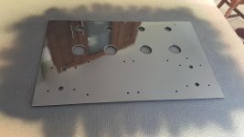
I've got the metalwork and the wooden chassis ready.
Deja Vue.
Here we go again.
I've got the metalwork and the wooden chassis ready.
Attachments
Last edited:
I can't seem to find anyone making a 240V / 320V 300mA transformer so I'm having to use 2 x 240V / 120V transformers, using three of the four secondaries to give me 360V.
Hence the need for the regulator.
The full amplifier then needs 4 x transformers. Two more for the 70V Cathode bias and the 6.3V heater supplies.
As I had the 240 / 120V and 240 / 6V transformers already, it's more cost effective just buy a 240 / 70V trannsformer (£20 on e-bay). They just use up a fair bit of chassis real-estate.
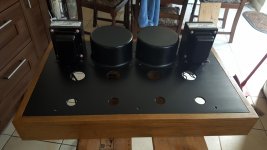
Aesthetically it's OK. The two 240 / 120V toroids are on the top of the chassis between the OPTs inside cans. The other two are hidden under the chassis. As they are all toroids, the two smaller transformers are mounted under the bigger two.
Hence the need for the regulator.
The full amplifier then needs 4 x transformers. Two more for the 70V Cathode bias and the 6.3V heater supplies.
As I had the 240 / 120V and 240 / 6V transformers already, it's more cost effective just buy a 240 / 70V trannsformer (£20 on e-bay). They just use up a fair bit of chassis real-estate.
Aesthetically it's OK. The two 240 / 120V toroids are on the top of the chassis between the OPTs inside cans. The other two are hidden under the chassis. As they are all toroids, the two smaller transformers are mounted under the bigger two.
Last edited:
Has anyone ever seen "valve base extenders" ?
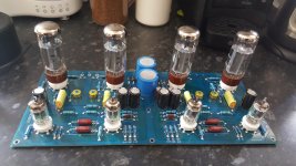
In my application the tube sockets are mounted on the top of the PCB. The capacitors then necessitate the use of 40mm spacers so that the PCB can be mounted under the chassis.
That's OK for the EL34s, enough of them poke through to make them visible.
The 12AU7's - I only get to see half the tube envelope.
What about 600V CT say 372JX Hammond. If you go CT there's quite a big range. Toroidy have some too. If you search for Mullard 5-20 stereo HT Transformer.
https://www.hammfg.com/files/parts/pdf/372JX.pdf
https://www.hammfg.com/files/parts/pdf/372JX.pdf
Last edited:
Has anyone ever seen "valve base extenders" ?
In my application the tube sockets are mounted on the top of the PCB. The capacitors then necessitate the use of 40mm spacers so that the PCB can be mounted under the chassis.
That's OK for the EL34s, enough of them poke through to make them visible.
The 12AU7's - I only get to see half the tube envelope.
Mount the caps on the underside of the PCB and use smaller spacers? That's what I've always done.
Great idea! I put the valve sockets on the other side before but of course that requires a mirror layout of the valve.
As the PCB is pre-assembled and double sided I didn't really want to remount the caps.
I've found the socket savers, thank you.
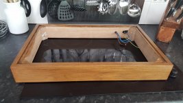
I'm pleased with how the chassis is turning out.
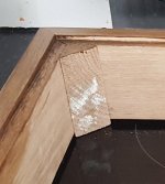
There is a slight stain from the wood filler on the rear of the woodwork that I didn't notice until the varnish dried, never mind, it is out of sight.
Today's task is to build and test the 450V regulator.
I've found the socket savers, thank you.
I'm pleased with how the chassis is turning out.
There is a slight stain from the wood filler on the rear of the woodwork that I didn't notice until the varnish dried, never mind, it is out of sight.
Today's task is to build and test the 450V regulator.
Attachments

A bit of advice needed from more experienced carpenters
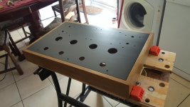
At the moment the metal chassis is just a tight fit in the woodwork.
If I was foolhardy enough to pick up the amplifier upside down, the weight of the transformers would easily pull the metal work out.
The woodwork is genuine Oak.
Where would you put the screws to hold the two together ?
I've got 4 x nice brass topped screws.
I was thinking about the corners but the wood is not at its' strongest there.
Attachments
Last edited:
Aha ! I've been waiting for several components to arrive and for some days off.
The parts have arrived and I've got 6 days holiday.
Tomorrow I will build and test the Maida style regulator and give it a test.
The parts have arrived and I've got 6 days holiday.
Tomorrow I will build and test the Maida style regulator and give it a test.
This project is very heavy. It contains 6 x transformers.
2 x OPTs
2 x 160VA toroids providing the B+
1 x 50VA toroid providing the HTR supplies
1 x 50VA toroid providing the 100V bias supply
The two main toroids are on the top of the chassis, the two lesser ones share the same real estate underneath the chassis.
2 x OPTs
2 x 160VA toroids providing the B+
1 x 50VA toroid providing the HTR supplies
1 x 50VA toroid providing the 100V bias supply
The two main toroids are on the top of the chassis, the two lesser ones share the same real estate underneath the chassis.
Last edited:
Hmm, the Maida regulator isn't working as planned.
Initially it emitted a tiny bit of magic smoke - I'm not quite sure where from ??
If you recall, I've adjusted some component values because I need 500V in and 450V out.
I've reduced R1 from 100K to 39K to keep the bias on D1. It might be D1 that cooked ?
R4 is a problem. In the original design this was 13K 2W for 150V out.
I calculated that I needed R4 = 42K which I made out of 3 x 10K + 1 x 12K all 3W.
They get so hot that they melt the solder joining them together.
The R4 combination never quite managed to go open circuit but it was close.
The regulator works to a fashion, it is dropping 30V but I can't use it as it is.
I've found a solution to my B+ problem.
Originally the B+ (AC) was being provided by two transformers, each with 2 x 120VAC secondaries, one unused so approx 360VAC.
Now I've swapped out one of those transformers for a 70VAC unit.
All secondaries in series now gives me a lovely 320VAC with 300mA load.
This is what the schematic shows.
Originally the B+ (AC) was being provided by two transformers, each with 2 x 120VAC secondaries, one unused so approx 360VAC.
Now I've swapped out one of those transformers for a 70VAC unit.
All secondaries in series now gives me a lovely 320VAC with 300mA load.
This is what the schematic shows.
With the 300mA load I get B+ at 422VDC.
That is less than the 450V that I was expecting.
The amplifier is not complete yet so that is just a lamp load.
Does 422VDC sound about right for this design ?
I don't think the amps draw 300mA, more like 200 - 250mA.
That is less than the 450V that I was expecting.
The amplifier is not complete yet so that is just a lamp load.
Does 422VDC sound about right for this design ?
I don't think the amps draw 300mA, more like 200 - 250mA.
Last edited:
- Home
- Amplifiers
- Tubes / Valves
- Building a Williamson EL34 amplifier