Fixed bias means the cathodes are at about 0V, so Vak is significantly higher for idle. What valves are you using, as that will dictate the dissipation limit. Do you know how to calculate dissipation watts?

Looks good, I would not bias the output tubes too hot say 40-50ma. I added a 47p in series with the 22k feedback resistor to get the HF stability with the Hammond transformer. Its a 1650R rather than an H but will be quite close. LF stability looks good. Output 20V pk into 8R.

View attachment 931387
Looks good, I would not bias the output tubes too hot say 40-50ma. I added a 47p in series with the 22k feedback resistor to get the HF stability with the Hammond transformer. Its a 1650R rather than an H but will be quite close. LF stability looks good. Output 20V pk into 8R.
I trust you meant in parallel with the NFB resistor.
Yep in parallel (C9 in ltspice) check when you get to that with a 1KHz square wave. There's already a dominant pole so some thought went into the design. I found the plate voltage on U1 a little low. You may wish to make the plate resistor 33k instead of 47k. I showed the UL version with KT77 as you have the UL taps and it will give you more power, but start with the triode mode and go with what you wish. You are limited to 450V max HT and for the EL34 430V might be better for vg2. I would keep away from max plate at 25W at that HT and run them a bit cooler say 40ma each.
Last edited:
My EL34s are 2 x matched twins for a Marshall.
They don't have a makers name but are marked WK03/09 so I presume they are modern 2009 tubes.
They don't have a makers name but are marked WK03/09 so I presume they are modern 2009 tubes.
Attachments
Last edited:

A friend of mine has put the instructions through another translation program. These make slightly more sense except for the bit about setting the bias with the NFB disconnected (or connected).
Attachments

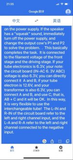
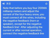
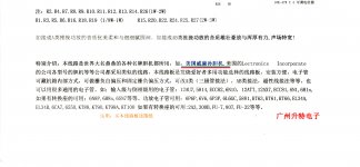
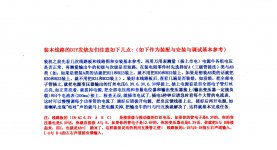
Can anyone throw any light on what they mean on Page 3, the large centre image in the top row above.
At a guess they mean connect the 0V return for the OPTs back to the PCB but do not connect the 2 x NFB loops. Only connect the NFB loops after the bias has been set.
There is no mention of the bias current ?
Previous comments have suggested somewhere around 40mA.
At a guess they mean connect the 0V return for the OPTs back to the PCB but do not connect the 2 x NFB loops. Only connect the NFB loops after the bias has been set.
There is no mention of the bias current ?
Previous comments have suggested somewhere around 40mA.
Last edited:
You appear to be about to set up multiple items of circuitry - any of which could have a problem.
How do you know your basic filtered B+ will be about 500V? Do you have a variac, or some way to initially reduce B+, so that you don't need to use the B+ regulator (so that you can confirm and set up the amp circuitry)? A variac, or a step-down transformer, allows the amp to start up with much less chance of faults or gross incorrect bias settings or ...
If you are then going to introduce a B+ regulator, it is initially worthwhile setting the bias so that output stage valve dissipation is quite low. What tools do you have to confirm the regulator is operating adequately?
If something goes wrong with an EL34 and it conducts heavily, what protection do you have for the OPT, regulator and PT ?
Last edited:
The problem is those SOA curves for switching type mosfets are often a lie. Almost all mosfets have some degree of second breakdown type behavior, and only *some* data sheet curves show it. Newer low Qg types are far worse about it than older, lower speed, lower voltage types like the IPRP240. To minimize your problems with the newer types, use devices with a moderate current rating and a high Rds(on). You don’t need . 02 ohm Rds(on) for a tube voltage regulator. Upwards of an ohm is fine. They will handle a larger portion of their power ratings at high voltages compared to the “best switch you can get” type.
This is the best piece of advice on the regulator in the entire thread, ive been trying to explain that
Can anyone throw any light on what they mean on Page 3, the large centre image in the top row above.
There is no mention of the bias current ?
Previous comments have suggested somewhere around 40mA.
"The circuit board is a fever." Gotta love translation programs.
There's no reason to disconnect feedback to measure idling current. It's measured as voltage across the output valves' cathode resistors, just add Ohm's Law and you're golden. I'd think 40mA would be great, but your B+ is pretty high for Chinese valves.
YOS,
Chris
Heathkit Schematic
That is a Heathkit W-5M
This is probably closer to the actual schematic.
I'll have to wait until the actual schematic arrives and then source some ECC82's.
That is a Heathkit W-5M
Your OPT is 6k6ohm PP, and the schematic shows 5kohm PP, so at some stage you may want to confirm the level of feedback being applied, and possibly modify R3 to get to 20dB mid-band.
The high frequency stability is likely to be ok, as the OPT is known, and the pcb includes the R10-C3 step network, and you may have a scope to optimise square-wave response using a cap across R3.
However there is still some doubt about the low frequency stability, which is a lot trickier to characterise. The OPT does appear to have a high primary inductance, which should help push the transformer related LF resonance well below the C1-R6 and C4-R17 roll-off responses, although C1-R6 corner is about 1Hz which is quite low and so may be a lurking problem.
You may want to check the resistor tolerances are 1% for R4-R11, and R12-R13, and R24-R25. If you have a capacitance range on a meter then you may want to check tolerances of C1-C2 and C4-C5.
The EL34s were previously tried in a Maplin Millenium build so I am confident they are not short circuit.
The PSU was used in the Maplin Millenium and happily provides 500V at 250mA+.
I can test the regulator into a lamp load.
Unfortunately I don't have a variac.
All the resistors are 1%.
The PSU was used in the Maplin Millenium and happily provides 500V at 250mA+.
I can test the regulator into a lamp load.
Unfortunately I don't have a variac.
All the resistors are 1%.
Last edited:
The simulation with the nearest transformer I measured is OK backing up your LF statement. The HF needs about 33p across R3 to improve the phase margin. I found C3 could be a bit bigger say 150p. I tested amps before without a variac by putting a halogen light bulb in series with mains input. If it starts to dim you are usually OK.
You will have a variac even better for future projects too.
You will have a variac even better for future projects too.
Last edited:
I'm not over familiar with valves but I guess that "Plate dissipation" would be calculated as the voltage across K - A multiplied by IA.
- Home
- Amplifiers
- Tubes / Valves
- Building a Williamson EL34 amplifier