Hi
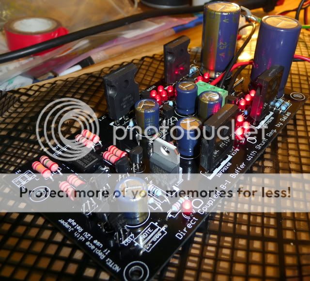
I've finished stuffing the board and everything appears to be OK.
I am getting +10.17v and -9.52v at the shunt output, and the DC offset is R=0.1mV and L=0.2mV when idling. It does occasionally rise a bit when turning on or off, but I understand this is to be expected. The relay also clicks-in after a few seconds. I will be using this with my F5 so I'll be adding a 1uf cap on the amps input.
Is there anything else I should check before connecting my LDR attenuator?
Thanks
I've finished stuffing the board and everything appears to be OK.
I am getting +10.17v and -9.52v at the shunt output, and the DC offset is R=0.1mV and L=0.2mV when idling. It does occasionally rise a bit when turning on or off, but I understand this is to be expected. The relay also clicks-in after a few seconds. I will be using this with my F5 so I'll be adding a 1uf cap on the amps input.
An externally hosted image should be here but it was not working when we last tested it.
Is there anything else I should check before connecting my LDR attenuator?
Thanks
Last edited:
check the voltage drops across the CCS resistors.
check the output offset from OFF to ON and from cold to operating temp.
The relay should be open when the circuit starts up and open again when the circuit shuts down. You should not see a DC pulse at startup nor at switch off.
1uF for a DC blocking cap seems quite low in value for the input of a Power Amp.
Are you intending to EQ the bass for a particular sound effect?
1uF for a DC blocking cap seems quite low in value for the input of a Power Amp.
Wouldn't that just depends on the input impedance resistor to ground? An RC filter will be affected by both the resistance and the capacitance...
Hi
I thought 1uf was the correct value for an F5. I'm sure I have seen it mentioned elsewhere. But if I'm wrong...
http://www.diyaudio.com/forums/pass-labs/145201-building-symmetrical-psu-b1-buffer-90.html#post2059999
All of the LEDs measured 1.8v when testing prior to soldering, the relay clicks after 5 seconds after turn on, and clicks again straight after switch off.
I measured the voltage across the 2x68R (34R) resistors. Negative side 1.76v and positive side 1.64v
I've just rechecked the dc offset whilst 'cold' and there doesn't appear to be any, just a slight bit of interference from the DMM. I will check the 'hot' readings a little later. 🙂
Last edited:
2.2uF would work even down to a 20k Zin amp.
Recommended by Salas in the Blue Hypno thread ; post 217 and working well with my DCB1 and Aleph 5.
Marra
Recommended by Salas in the Blue Hypno thread ; post 217 and working well with my DCB1 and Aleph 5.
Marra
Looks like working perfectly OK Richard. Congratulations. In the graph is the high pass you can expect when coupling 1uF to 100K load.
Thanks Salas. That graph looks good?
If your speakers can go lower than 1.8Hz -3dB then its not enough.😀
Seriously, you may use more uF for even less infrasonic phase shift but for sheer amplitude you are way well covered for 100K input F5 as you see in the graph.
Seriously, you may use more uF for even less infrasonic phase shift but for sheer amplitude you are way well covered for 100K input F5 as you see in the graph.
Have a proper look.Thanks Salas. That graph looks good?
That graph of low frequency response is for 1uF & 100k.
The output of your circuit is already loaded with 100k.
To achieve that graphed response the following Power Amp or receiver needs to have Zin = infinity.
If the actual Zin = 100k, then the resultant load for the HP filter is 50k. This moves the graph one octave to the right.
The F5 has no DC blocking cap at it's input so the 1uF works alone.
The Zin ~ 101k.
This leaves the HP filter F-1dB ~3Hz.
This is OK for many.
If as stated earlier, a Zin=20k were used then F-1dB moves to ~17Hz.
If that Zin=20k power amp had a capacitor of 4u7F as a DC blocker then F-1dB moves to ~22Hz
Summarising:
1uF at the source output only suits very high Zin at the receiver that is DC coupled.
Last edited:
To clarify the graph: The 100k was to simulate F5's published 100K Zin. Practically it would be DCB1, 1uF cap, 1Meg or more to ground, RCA, F5. 91K total if with 1Meg after cap to ground.
Hi
I have 3.3 or 4.7uf caps to hand if you feel either of these will measure better. I'm happy to purchase a different value if required.
I have 3.3 or 4.7uf caps to hand if you feel either of these will measure better. I'm happy to purchase a different value if required.
perfect!
Build up the source with the 1uF temporary tacked on.
Listen and evaluate.
ADD the 3u3F, also tacked on.
Listen and evaluate.
Was there any difference in the sound before and after?
Choose which you prefer and solder in permanently.
Build up the source with the 1uF temporary tacked on.
Listen and evaluate.
ADD the 3u3F, also tacked on.
Listen and evaluate.
Was there any difference in the sound before and after?
Choose which you prefer and solder in permanently.
perfect!
Build up the source with the 1uF temporary tacked on.
Listen and evaluate.
ADD the 3u3F, also tacked on.
Listen and evaluate.
Was there any difference in the sound before and after?
Choose which you prefer and solder in permanently.
Will do. Good idea 🙂
then try mix and match if you believe this is an issue.
I believe it is far more important that the input filtering is of narrower bandwidth than the amplifier/pre-amplifier can reproduce well.
eg. setting the amplifier input filtering to F-3dB @ 3Hz and 200kHz, requires the amplifier to work well over the bandwidth of 1.5Hz to 400kHz.
I believe it is far more important that the input filtering is of narrower bandwidth than the amplifier/pre-amplifier can reproduce well.
eg. setting the amplifier input filtering to F-3dB @ 3Hz and 200kHz, requires the amplifier to work well over the bandwidth of 1.5Hz to 400kHz.
Guitar Pedals: R-C Filter Calculator
You figure you want your -3db to be 2 octaves out from what your system can reproduce to get rid of phase problems.
Hes got 100k in:
for full range (odds are highly unlikey either his music or his speakers can produce)20-20k
input cap would be 0.318uf for 5 hz
my simple calc wont do ultra sonic calcs.
Hi
I have just finished wiring my L/S attenuator into the DCB1 and I appear to have some DC on right output channel, left appears fine.
When I turn on the attenuator and DCB1 at the same time the right channel peaks at ~1.4v before the relay clicks in, and then drops to 0v after the 5 second click. When I turn it off the right output peaks at ~800mV and very slowly decreases. As I am only in the checking phase I haven't connected it to my amp...thankfully 😛
Any ideas?
Thanks
What happens if you are turning them on in separate times?
Hi Salas
It happens if I turn on the DBC1 first, the L/S doesn't make any difference.
Last edited:
- Home
- Amplifiers
- Pass Labs
- Building a symmetrical PSU B1 buffer