I'm not sure, I would like to think that it contributes positively, surely it does. The slightly low voltage output may be helpful here also, pushing the "pot" resistance up, easing source impedance constraints just a bit? Still drives these buffers in parallel with no problem at all (110k input). This pre hides nothing, tremendous resolution, and is showing me weaknesses with the rest of my system, poor source mainly which will get attention at some point. Another area of interest, different music / production technique is more "contrasted" than before. Hard to explain but I think it's another clue that the system has taken another step or two up, and is "getting out of the way". Does this make sense?
I'm certainly hypnotized and mezmerized..... several hours per night in fact for the past month....
I'm certainly hypnotized and mezmerized..... several hours per night in fact for the past month....
The more you can differentiate score clues it means that the brain is at better ease with the sonics. Yes, surely positive.
At 100mA you get some of the benefit. If you can get some MKP 1837 Vishay 10n or FT-1 22nF CCCP Teflon, just bypass the 5 string shunt 100uF lytics underneath pcb, keeping short legs. But not the output lytics. That one you may hear easy and decide, without hacking or altering visually the nice build.
Just to clarify, is bypassing the lytic better or replacing with a MKP of film cap? Is the capacitance important? Can solder to the ends of the LED chain instead of the lytic position?
You mentioned it doesn't sound its best until a couple of hours, why is this so? I'm not really in favour of leaving it on 100%, so any way to avoid this? Esp since bumping up the current to over 200ma will also reap benefits! 😀
I don't think I am understanding your question, a way to avoid what? burn-in and reforming of capacitors?You mentioned it doesn't sound its best until a couple of hours, why is this so? I'm not really in favour of leaving it on 100%, so any way to avoid this? Esp since bumping up the current to over 200ma will also reap benefits! 😀
Transformer is an Antek AN-1212, works great, completely silent.
12-0-12, 100VA
LDR supply / front panel indicators have their own diode bridge (MUR120's, same as the DCB1's)
12-0-12, 100VA
LDR supply / front panel indicators have their own diode bridge (MUR120's, same as the DCB1's)
Transformer is an Antek AN-1212, works great, completely silent.
12-0-12, 100VA
LDR supply / front panel indicators have their own diode bridge (MUR120's, same as the DCB1's)
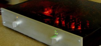
And how the orange front LED does work? What is it purpose for?
please gift me layout pcb power amplifier lm 3886 complite with componen.my email antoryans@yahoo.co.id thanks b 4
Just to clarify, is bypassing the lytic better or replacing with a MKP of film cap? Is the capacitance important? Can solder to the ends of the LED chain instead of the lytic position?
You mentioned it doesn't sound its best until a couple of hours, why is this so? I'm not really in favour of leaving it on 100%, so any way to avoid this? Esp since bumping up the current to over 200ma will also reap benefits! 😀
Replacing is purer than bypassing. To the ends of chain is better if no lytic is present. 0.22-1uF if alone, 10nF-22nF if a lytic bypass.
I could think of scenarios, but it will be pseudo science since I got no data. It seems to sound better later from power on to me and other people. That is the loose idea. Check for yourself, maybe its other things in our chains too.
regiregi22:
I talked about the orange LED at post #1295. It's not a necessary component of the LDR circuit. Just a personal touch kind of thing I came up with, gives the front panel a balanced but interesting contrast I think. And a friendly reminder to run the volume at half for a long, productive life of the LDR's when in "standby" mode.
Front LED's are run by an 8V regulator, with appropriate dropping resistors of course.
Sorry Williams, my fault. I'm sorry, I was writing a post while you were posting yours 😛 There are 2 minutes of difference between them.
Enjoy your preamp, seems to be one of the best out there actually.
Enjoy your preamp, seems to be one of the best out there actually.
I want to modify the DCB1's regulator to deliver +-24V needed for a small preamp as well.
Can I use the symmetrical B1 buffer with +-24V so I can use the regulators for both?
Thanks,
Zsolt
Can I use the symmetrical B1 buffer with +-24V so I can use the regulators for both?
Thanks,
Zsolt
Last edited:
My B1 fired up for the first time perfectly with no apparent issues. Can anyone recommend a brief list of checks before I plug it into my system?
Regards,
Dan

Regards,
Dan
-First, short the inputs to ground and measure the outputs. Set your DMM to mv AC, and you should see it virtually zero. Then on mv DC you should see no more than 5mv or so. Try rotating you volume control to see if it changes
-Second, connect your source to it, and check the same things. Values should stay more or less the same.
-Third, hook up some cheap speakers to the amp before hooking your expensive ones.
-Second, connect your source to it, and check the same things. Values should stay more or less the same.
-Third, hook up some cheap speakers to the amp before hooking your expensive ones.
I want to modify the DCB1's regulator to deliver +-24V needed for a small preamp as well.
Can I use the symmetrical B1 buffer with +-24V so I can use the regulators for both?
Thanks,
Zsolt
Not recommended. Each audio JFET will reach 250mW constant dissipation. Very precarious for 400mW max TO-92 devices. Especially here if one goes, opposite rail DC appears at the output.
-First, short the inputs to ground and measure the outputs. Set your DMM to mv AC, and you should see it virtually zero. Then on mv DC you should see no more than 5mv or so. Try rotating you volume control to see if it changes
-Second, connect your source to it, and check the same things. Values should stay more or less the same.
-Third, hook up some cheap speakers to the amp before hooking your expensive ones.
First very quick measurements are: PS is +10.86vdc and -10.17vdc. DC offset on the outputs appears to be .2mV and 1.0mV. I'll do the rest tomorrow.
Regards,
Dan 🙂
What about using TO-92 clip-on heatsink? like one of these:Not recommended. Each audio JFET will reach 250mW constant dissipation. Very precarious for 400mW max TO-92 devices. Especially here if one goes, opposite rail DC appears at the output.
TO-92 Heatsink
Digi-Key - HS251-ND (Manufacturer - 575200B00000G)
that will help power dissipation and temperatures, but you still have the risk of 48Vds on either device. How long will jFETs last with 48Vds and running hot?What about using TO-92 clip-on heatsink? like one of these:
TO-92 Heatsink
Digi-Key - HS251-ND (Manufacturer - 575200B00000G)
- Home
- Amplifiers
- Pass Labs
- Building a symmetrical PSU B1 buffer