Just wondering...
Ben, I agree with you that the wiring to ground needed to change. But it seems to me that the ideal point of connection should have the fewest joints en-route to the safety of ground. In other words in this case where an IEC socket is employed I'd have wanted to make the connection there. I do see that this socket doesn't really have the facility... but maybe it should.
Electrical panelboards have a bus bar with lots of connection points so that connections and wires are not shared. There are rules about not running two wires into a breaker too.
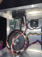
I'm in the process of renovating an old power supply (for my 1980 Leach preamp) and one of the changes I'm considering is changing the power cord to three-wire. The end of that green wire is the bull's eye target -- safety-grounding wise -- to which the chassis ought be connected but also the signal (I've got a bridge too). Maybe there's a short ground bus bar that will realize this ideal. Or is that "notion"?
Thoughts?
Ben, I agree with you that the wiring to ground needed to change. But it seems to me that the ideal point of connection should have the fewest joints en-route to the safety of ground. In other words in this case where an IEC socket is employed I'd have wanted to make the connection there. I do see that this socket doesn't really have the facility... but maybe it should.
Electrical panelboards have a bus bar with lots of connection points so that connections and wires are not shared. There are rules about not running two wires into a breaker too.
I'm in the process of renovating an old power supply (for my 1980 Leach preamp) and one of the changes I'm considering is changing the power cord to three-wire. The end of that green wire is the bull's eye target -- safety-grounding wise -- to which the chassis ought be connected but also the signal (I've got a bridge too). Maybe there's a short ground bus bar that will realize this ideal. Or is that "notion"?
Thoughts?
I don't think manufacturers of EIC sockets would want to take responsibility of ensuring an effective and reliable direct connection of their socket earth ground to chassis ground.
For diyers, I think that the simplest and best chassis ground point is implemented with a long screw or bolt that is fastened to the chassis with star washers and nuts, and the earth ground wire from the IEC socket terminated with a ring terminal that is fastened to the screw with a star washer and nut. The other ground wires then go on top of that.
With the earth ground wire at the bottom of the stack, it cannot be removed unless the other wires are removed.
Another safety consideration is that all metal conductive panels of a chassis need to be electrically connected. Many if not most anodized chassis and their heat sinks are put together with anodized screws, with a questionable electrical connectivity between all parts. Chassis panels and heat sinks should be checked for electrical connection to chassis safety ground. Parts may need sanding to ensure that every part of the chassis is able to conduct electricity to chassis safety ground.

My point is that what makes the chassis ground safe is that wire to the IEC ground pin no matter how you wire up the rest.
Or am I missing a path?
Or am I missing a path?
Just to provide a little context. My experience with "nuts on nuts"... especially with lock washers has been that attempts to remove just the top one often results in disturbing the bottom one. "All Thumbs Are Us".
Everything's fine so long as you don't mess with it once it's attached (although my preference would be to reduce contacts.... especially serial ones).
I still like the idea of a ground buss (sp?).
Everything's fine so long as you don't mess with it once it's attached (although my preference would be to reduce contacts.... especially serial ones).
I still like the idea of a ground buss (sp?).
Pass DIY Addict
Joined 2000
Paid Member
shomescu: After checking the voltages that Dennis has recommended, I would recommend having another look at the back side of your PCBs. This board is notoriously difficult to work with due to the ground plan on the bottom - essentially, the bottom layer of the board is one giant sheet of copper which will work very effectively to wick away the heat from your soldering iron. This makes good solder joints difficult to achieve. If you are using a 25-40w "pencil" iron with a fine tip, this makes assembly of the board even more difficult because the heat output of these irons is relatively small.
I would recommend using an iron with higher heat output (which then means you have to work more carefully so you don't cook your parts. A small "clip on" heat sink attached to the legs (on top of the board) of the devices you are working with can help prevent over cooking them. You want to make sure that the copper plate on the bottom of the PCB is good and hot so you get a good solder joint.
Another trick that I use after populating a PCB is to take a micro screw driver (flat blade) and physically scratch around all of your solder joints to make sure that you didn't get a small little blob of solder that is causing a short somewhere on the board. Use a bright light and a magnifier to make sure you can see everything clearly as you work. After you've done this, then use some flux remover to clean the bottom of the board. I've had a few problems because of my sloppy work in the past...
At this point, I am inclined to think you have one of three problems:
1) Wrong part value. Always double check ALL resistor values - measure them (don't trust the label on the bag) - before inserting into a PCB.
2) Cold solder joint means that a connection somewhere in the circuit is missing. Reflow all of the joints that were difficult to make.
3) Inadvertent solder bridge where it doesn't belong. Scratching around the solder joints will likely remove this problem.
4) Carefully inspect with a bright light and a magnifier.
5) When doing a first power-up, only power one channel at a time. If you did something wrong, it's better to toast one board than two at once...
Your voltage regulators should not feel warm/hot to the touch. This means something is still wrong. Current draw for this circuit is 21mA on the negative rail (per board) and 42mA on the positive rail (per board).
Last edited:
To augment Eric's good advice I would add:
1. Both bottom and top of your boards deserve some attention. Cleaning means cleaning off the flux... removing it.
2. Refreshers on soldering technique are germane. Indeed, in his first Pearl article, Wayne offered basic advice that included securing the part leads in the holes so that the part doesn't shift when you press the tip of the soldering iron to the lead and the pad to heat them. You don't want the part to move as you take away the iron and before the solder hardens. On the other hand solder flows onto a well-heated joint better and that takes good contact of both lead and pad with the iron tip.
I would appreciate your thoughts on troubleshooting a problem that has developed with my recently completed Pearl 2. The unit had been working great up to this point. However, when I went to listen last night, one channel was hardly putting out any sound, and what was coming out was scratchy and intermittent. I isolated the problem to the phono by confirming that other components were working fine. I also checked for bad cables or connections (which was the first thing that occurred to me given the symptoms), and found none. That is all the checking I have done so far.
I am hoping for suggestions on where to continue/prioritize my troubleshooting efforts.
I am hoping for suggestions on where to continue/prioritize my troubleshooting efforts.
If you are getting some sound (music), but low volume and intermittent, it may be a bad solder joint somewhere. Closely examine all of the joints and redo any that looks suspicious.
you can tap around with a stick of wood at the pcb carefully and
listen if something changes..........
listen if something changes..........
Pass DIY Addict
Joined 2000
Paid Member
This is my guess as well - a cold solder joint somewhere on the bottom of your board. The ground plane is large and makes achieving good solder joints something of a challenge. Gently tapping on one component at a time as suggested (use the eraser end of a pencil) to see if that provides any changes. Failing that, carefully reflow the solder joints.
Last edited:
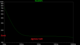
BumpWhat is the output impedance?
I know it's at least 10R 😀
In LTSpice, hang a current source on the output AC=1, and measure V(out)/I(out):What is the output impedance?
I know it's at least 10R 😀
Attachments
I just got a new cartridge (0.5mV) and I need a little more gain out of my Pearl 2 now.
(0.5mV cart, 562 Av Pearl 2 phono, 6.3 Av preamp, 2.83V input sensitivity power amp)
My Pearl 2 is currently configured for 55dB of gain with R14 = 1K.
I need about 60dB from the Pearl 2. I know NP mentions in his article that changing R14 to 300R will get you 65dB but what about 60dB?
What value in between 1K and 300R would get me 60dB of ?
- Home
- Amplifiers
- Pass Labs
- Building a Pearl 2