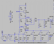
Jack, what is the purpose of raising R9?
Is it not sufficient to lower R5 and change R8/R10 ratio in order to achieve preferred bias?
Is it not sufficient to lower R5 and change R8/R10 ratio in order to achieve preferred bias?
Gain -- pick a value to suit your purpose.Jack, what is the purpose of raising R9?
I had posted this in the other pearl 2 thread but figured I would try here:
I am still loving the pearl two but have a question as I changed both my table and my cartridge. I restored a TD-124 and am using a Denon DL-103 cart. I replaced the 47k resistor with a 100 resistor but when I measure across the inputs I see a load of 28 or so ohms. I have the zobel installed and am wondering if this is what is causing it? I would think in parallel the resistance would still be higher than 28 given the zobel resistor is 680 ohms. Any guidance? Anyone else using the 103 with the pearl 2?
I am still loving the pearl two but have a question as I changed both my table and my cartridge. I restored a TD-124 and am using a Denon DL-103 cart. I replaced the 47k resistor with a 100 resistor but when I measure across the inputs I see a load of 28 or so ohms. I have the zobel installed and am wondering if this is what is causing it? I would think in parallel the resistance would still be higher than 28 given the zobel resistor is 680 ohms. Any guidance? Anyone else using the 103 with the pearl 2?
I had posted this in the other pearl 2 thread but figured I would try here:
I am still loving the pearl two but have a question as I changed both my table and my cartridge. I restored a TD-124 and am using a Denon DL-103 cart. I replaced the 47k resistor with a 100 resistor but when I measure across the inputs I see a load of 28 or so ohms. I have the zobel installed and am wondering if this is what is causing it? I would think in parallel the resistance would still be higher than 28 given the zobel resistor is 680 ohms. Any guidance? Anyone else using the 103 with the pearl 2?
Are you measuring between the center pin and ground of one channel's RCA connector? I have the zoebel, and mine measures 100 ohms.
connector and grounding question
While I wait for the chassis, some questions came to my mind which you can certainly answer.
I bought this amphenol plugs and connectors for the psu/amp connection. These have a ground lug, now I'm not sure whether I should connect them to the chassis or to earth ground or leave it?
The same also with the power cord. I have a 4-conductor wire for this (canare 4s6). Should I connect the 4th strand to the ground lug of the connector or connect it to a pin and leave it "blind"?
thanks in advance,
jules
The Pearl 2 doc talks about this at the end in the PS section.
Thanks McQuaide, I'll study it again.
I've already assembled the power cable let's see how well this works.
I've already assembled the power cable let's see how well this works.
Voltage Offset with R14 and Cap mod
Hi,
I have just completed building the Pearl2 from the official boards and have a question regarding the voltage offset. I have read through this thread and some others and can't find the answer I'm looking for, though I may have missed it; my apologies if I have.
I have a 220uF cap on the GND side of R14 as per the posts on that topic. I measure at the voltage offset pad 35mV on one board and 55mV on the other. These voltages are stable over time, with no input signal and with an input signal. If I adjust P1 the voltages move (up or down depending on the direction I adjust P1) but immediately return to 35mV and 55mV respectively. Both boards test fine on the bench and appear to behave as designed (small signal in, large signal out).
My questions:
1) Is 35mV and 55mV close enough to 0 volts for the Pearl 2 or should I be trying to get closer?
2) Should they be matched in value even if not exactly 0?
3) If I should adjust them closer to 0V how should I go about doing this?
Many thanks for any assistance.
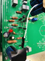
Can you post a picture of your build? I think that 35/55mV is a bit high there.
Without the cap, there could be some fluctuations, but with it, it should be very close to 0.
Without the cap, there could be some fluctuations, but with it, it should be very close to 0.

almost finished
Hello everybody
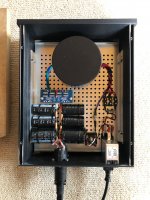
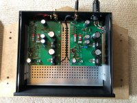
I finished the amplifier today and connected it for the first time. The turntable is a technics sl-1210gr with a benz micro ace sl. Loading is 100 ohm and gain 350 ohm.
Sounds fantastic!
But i'm not quite happy yet. I have a strange hum which I can't fix.
Maybe you have an idea what it could be?
thanks,
Jules
Hello everybody
I finished the amplifier today and connected it for the first time. The turntable is a technics sl-1210gr with a benz micro ace sl. Loading is 100 ohm and gain 350 ohm.
Sounds fantastic!
But i'm not quite happy yet. I have a strange hum which I can't fix.
Maybe you have an idea what it could be?
thanks,
Jules
Attachments

But i'm not quite happy yet. I have a strange hum which I can't fix.
Maybe you have an idea what it could be?
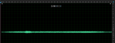
Motorboating -- you have a pulse every 100 milliseconds. Check C21/R25/D1.
Attachments
Last edited:
Hi jackinnj
checked the voltages and they look good to me.
Right side -22.1v, left side -22.0v.
Can it be related to the power from the house?
It's very old.
checked the voltages and they look good to me.
Right side -22.1v, left side -22.0v.
Can it be related to the power from the house?
It's very old.
short the input, then if you have a scope, you can probe backwards from the output node to see the origin.
i think that you are the first to report this as an issue.
i think that you are the first to report this as an issue.
Hello
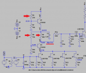
After implementing the cap mod at r14 (which involved removing the boards) , I have near 0mv. However I have lost output form one board, only a very faint sound present, the led lights up.
I have Wayne's schematic form Dec 2011.
At which points should I be looking.
After implementing the cap mod at r14 (which involved removing the boards) , I have near 0mv. However I have lost output form one board, only a very faint sound present, the led lights up.
I have Wayne's schematic form Dec 2011.
At which points should I be looking.
little update
So the power line filter made no difference. Atleast the power from the house is good.
What I found out is, if I'm touching the ground from the rca input motorboating and a little bit of noise goes away.
Also if ground cable from turntable is connected I get 50hz hum.
Checking every solder joint again today and maybe replace red ground cable in riaa section. The cable is not my friend.
I have begun work on my Pearl 2 Project
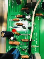
I have one question regarding parallel capacitors c12 and c16, which are two 0.1 uf caps to make 0.2 uf in total, is there any reason I couldn't use one 0.22 uf cap instead? I have some 0.22uf Audyn Copper caps which I think will work well there. Has anyone noticed improvement using a upgraded cap in that position compared to Wima MKP?
.jpg")
I have one question regarding parallel capacitors c12 and c16, which are two 0.1 uf caps to make 0.2 uf in total, is there any reason I couldn't use one 0.22 uf cap instead? I have some 0.22uf Audyn Copper caps which I think will work well there. Has anyone noticed improvement using a upgraded cap in that position compared to Wima MKP?
- Home
- Amplifiers
- Pass Labs
- Building a Pearl 2