Hey gang, I need some help. I have had a Pearl II running successfully for about 6 months now. I changed the gain on it, and changed the loading resistor at a friends house and now there is a distinct hiss that sounds like white noise in one channel. It wasn't doing this before I brought it back home. The weather was extremely cold so I don't know if that had anything to do with it, but it was still warm from being used when I put it in my car.
Any thoughts on where to start? I went ahead and re-flowed the solder joints on all components hoping to find a cold joint.
Thank you!
Any thoughts on where to start? I went ahead and re-flowed the solder joints on all components hoping to find a cold joint.
Thank you!
Hey gang, I need some help. I have had a Pearl II running successfully for about 6 months now. I changed the gain on it, and changed the loading resistor at a friends house and now there is a distinct hiss that sounds like white noise in one channel. It wasn't doing this before I brought it back home. The weather was extremely cold so I don't know if that had anything to do with it, but it was still warm from being used when I put it in my car.
Any thoughts on where to start? I went ahead and re-flowed the solder joints on all components hoping to find a cold joint.
Thank you!
Extremely cold weather -- means lots of static electricity. The output MOSFET is particularly prone to going "pffffft"
If you changed resistor values, you may need to adjust the trimpot and zero the voltage at the junction of R16/R17.
Extremely cold weather -- means lots of static electricity. The output MOSFET is particularly prone to going "pffffft"
If you changed resistor values, you may need to adjust the trimpot and zero the voltage at the junction of R16/R17.
That makes sense as well. It's dry in my house too so that's a likely suspect.
Another Pearl 2 finished
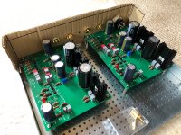
The Lady Pearl sings so beautifully. I could not be happier. I followed this build guide carefully. And I did not have any issue. My output mosfets are sitting on sockets. Mouser 535-08-0513-10H
And I made sure to buy some spares. I listened!
R14=1k+47uf gives me enough gain. I am playing with CS100 and it sounds beautiful.
6l6, I am grateful for your guide.
And the collective wisdom helped me a lot. Thanks everyone.
And Wayne thank you so much. This is beautifully designed phonostage.
I wonder if anyone is using step trans for MC carts.
Thank you all
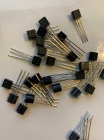
 ZVP3310.
Thanks for the correction! 😱
I don't recall that part of the circuit being discussed with significance (besides the occasional ESD failure of those parts).
What is the advantage in having them socketed?
I don't recall that part of the circuit being discussed with significance (besides the occasional ESD failure of those parts).
What is the advantage in having them socketed?
b/cWhat is the advantage in having them socketed?
occasional ESD failure of those parts
In case they fail I can just pull them out and plug new ones in. I am so not good at desoldering. 😀
just started
Hello everyone,
First of all, I would like to thank everyone who makes this possible! I'm so happy.
This is my third amplifier that I am building and a whole new challenge.
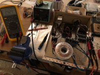
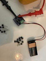
At this moment I tested the power supply and it works. yeah!
so much to read, so much to learn, so much fun
regards,
jules
Hello everyone,
First of all, I would like to thank everyone who makes this possible! I'm so happy.
This is my third amplifier that I am building and a whole new challenge.
At this moment I tested the power supply and it works. yeah!
so much to read, so much to learn, so much fun
regards,
jules
Attachments
b/c
In case they fail I can just pull them out and plug new ones in. I am so not good at desoldering. 😀
They won't fail from ESD once installed.
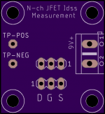
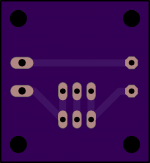
I made a small test jig for measuring Idss. Probably overkill but I like the convenience.
Has 2 test points to attach mini grabbers and terminal for PS or battery.
I have extras if anybody wants a "kit".
Also have alot of leftover 2SK170BL that I bought from bdent. Idss range from 8mA-11mA.
Has 2 test points to attach mini grabbers and terminal for PS or battery.
I have extras if anybody wants a "kit".
Also have alot of leftover 2SK170BL that I bought from bdent. Idss range from 8mA-11mA.
Attachments
Pass DIY Addict
Joined 2000
Paid Member
Pretty sweet board! I made my own many years ago, but it's no where near as nice and clean as yours. I used a DIP-8 socket, a few resistors, a small square of perf board, and screwed it down to a block of wood. I can measure both P- and N-ch devices.
Nice!
The label is misleading, it is for N-ch when connecting by the labels on the PCB, but if you swap the power and DMM leads then it should work for P-ch too.
The label is misleading, it is for N-ch when connecting by the labels on the PCB, but if you swap the power and DMM leads then it should work for P-ch too.
Now I can say something about the Pearl build
After having built it during the Xmas break and a lot of tinkering, though It had an intermittent issue in the left channel which turned into something insidious, hum, less output, no sound, etc., I finally found out what it was. A lesson to be learned; those solder joints have to be looked over carefully. It turned out that, even after a few revisions I had missed the unsoldered ground pin of the positive regulator.
So, after taking care of that and some suspicious joints, dressing the cabling in an organized manner, it is sounding beautifully. Very clear sound. A very spacious soundstage, very dynamic, lighting fast, and a lot of apparent details unnoticed before. This time Eric -thanks- helped me a lot with his guidance and patience of a professor he is.
Pass DIY Addict
Joined 2000
Paid Member
Very glad to hear that you got it sorted out, Manuel! Now sit back and enjoy your work!
When I run into a situation like this, my wife often tells me: "I'd tell you what the problem is, but then I'd deprive you of the thrill of discovering it for yourself!" She's very helpful like that 😉
When I run into a situation like this, my wife often tells me: "I'd tell you what the problem is, but then I'd deprive you of the thrill of discovering it for yourself!" She's very helpful like that 😉
First hookup of my second Pearl2 build, I think I'm having similar issues than some folks here.
The Idss of the JFET's is a bit high, around 8.5mA.
I'm getting 0.062V on R20-R24, so higher than 0.01-0.04 target but generally should be OK I think.
One issue though is that on Q3, Vc=7.78V, Vb=8.38V, Ve=7.64V , so Vc < Vb.
Should I decrease R10 from 10K ?
The Idss of the JFET's is a bit high, around 8.5mA.
I'm getting 0.062V on R20-R24, so higher than 0.01-0.04 target but generally should be OK I think.
One issue though is that on Q3, Vc=7.78V, Vb=8.38V, Ve=7.64V , so Vc < Vb.
Should I decrease R10 from 10K ?
- Home
- Amplifiers
- Pass Labs
- Building a Pearl 2