Thanks for your patience 6L6...but I am a little confused.
If I get you right, I can connect both center ground pads of the RIAA boards together, but not to the ground post.
The ground post is the only item connected to the chassis then?
If I get you right, I can connect both center ground pads of the RIAA boards together, but not to the ground post.
The ground post is the only item connected to the chassis then?
Both PCB ground is tie to phono shield ground post, that's the extra lug that the phono comes with.Thanks for your patience 6L6...but I am a little confused.
If I get you right, I can connect both center ground pads of the RIAA boards together, but not to the ground post.
The ground post is the only item connected to the chassis then?
Phono shield ground then tie to chassis.
Phono input ground especially the RCA connector is connected directly to board, make sure no connection to chassis at RCA, best verify before soldering cable to Pearl 2 board.
Ok... that is the way I thought I had everything hooked up... but I may have a stray connection that I should not...
Will check again and get back...
Thanks for all the help... at least I know what to look for now.
Just to confirm... The center ground on the RIAA does not have continuity with the signal ground on the board.
Will check again and get back...
Thanks for all the help... at least I know what to look for now.
Just to confirm... The center ground on the RIAA does not have continuity with the signal ground on the board.
Last edited:
Ground is ground is ground.
There is continuity at the center point of the board to the GND of the psu pads and the input and output grounds. It's all the same.
The trick is to keep it all floating off the chassis except for the grounding post, and the only connections to the posts are the center points of the PCBs. This keeps loops eliminated or at least so close in potential that there is no very unbalanced loop, which hums.
Helps if you disconnect the intentional chassis ground point and check for unintentional ground connectionOk... that is the way I thought I had everything hooked up... but I may have a stray connection that I should not...
Will check again and get back...
Thanks for all the help... at least I know what to look for now.
Just to confirm... The center ground on the RIAA does not have continuity with the signal ground on the board.
Ok...got it...
Will investigate... but will report back after vacation staring tomorrow. Probably won't get to it tonight.
Thanks a lot for all the assistance
Will investigate... but will report back after vacation staring tomorrow. Probably won't get to it tonight.
Thanks a lot for all the assistance
pearl parts upgrades
does anyone have a handle on which resistors or caps at critical
to the overall sound and would be the best candidates for upgrading? looking to tweak a bit and play with vishay nudes or different caps but not sure where to start.
thanks
does anyone have a handle on which resistors or caps at critical
to the overall sound and would be the best candidates for upgrading? looking to tweak a bit and play with vishay nudes or different caps but not sure where to start.
thanks
does anyone have a handle on which resistors or caps at critical
to the overall sound and would be the best candidates for upgrading? looking to tweak a bit and play with vishay nudes or different caps but not sure where to start.
thanks
use Vishay/Dale RN55/RN60 or CMF55 resistors. C13 -- you'd do well to use an Elna Silk -- all these are available from Mouser.
Q2-- ZVP3310 -- you will be well served if you handle this baby carefully as they are quite static sensitive.
Most critical from the standpoint of the passive RIAA filter is to match the capacitor values of each channel. You don't buy 2, you buy 10. Polypropylene preferred over polyester -- and you can use Mouser's search engine to get ones with the proper lead spacing.
I am convinced that the value of R12 is incorrect. Should be 990R, not 909R.
A 10K and 1K paralleled will give you 990 I think I had 909 in stock for something and used it. A bit of a hump but perfect for many speakers😉
Hi Wayne, do you mean a hump in the RIAA curve?
I'm a bit confused now...909R for a nice sound but 990R for a perfect curve... Is that what you are saying?
I'm a bit confused now...909R for a nice sound but 990R for a perfect curve... Is that what you are saying?
Late Happy New Year ...
Update... New problem.
So I now have a Benz Wood LOMC.
In the Pearl2 I loaded it with 1kohm and swapped 1kohm for 300ohm as indicated in this thread for increased gain...
The Right channel is all good, but now have a thin tinny sound from the left channel.
Turning up the volume with no music, I hear a high pitched whistle.
I checked all voltages and I think q1 was burned out, changed it but still no joy. Also changed q2 just in case.
Will keep investigating, but any suggestions would be appreciated.
Cheers
Thanks 6L6.Short the inputs, is the noise still there?
Actually... just solved the problem with the tinny sound... really silly.
The midrange and bass cable to the speaker had com loose at the amp... so just tweeters were getting signal.
Still some RF noise from speakers.. Will try you test and report back.
There is a light high pitched whine when inputs shorted.
I guess this is RF noise ...
I guess this is RF noise ...
Short the inputs, is the noise still there?
Advice voltages
Hi folks. I need some advice. I have an excellent, well tuned stereo system with the old Pearl 1 as phono preamp. The Pearl 1 is the weakest link in the chain and I have therefore built two Pearl 2 boards from Passdiy. From here the next steps are buying 2 cabinets for PSU and RIAA, and components for 2 separate top notch PSUs. This represents a nice sum and I only want to move on with the Pearl 2, if I am convinced that it will be an improvement.
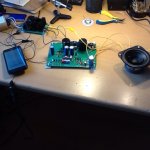
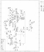
If I make a lowfi workshop setup (see picture), both boards make music, but I cannot of course judge quality on this setup. What worries me, is that when I measure voltages they vary significantly from waynes, and between the two boards (see the scan, circles for measurements on one board, squares for the other).
What do I do? Do I move on and ignore the fact that volts in one channel is about 20% higher (in the lower left corner)? And can I do anything to make the boards similar. Comments will be thankfully recieved.
Hi folks. I need some advice. I have an excellent, well tuned stereo system with the old Pearl 1 as phono preamp. The Pearl 1 is the weakest link in the chain and I have therefore built two Pearl 2 boards from Passdiy. From here the next steps are buying 2 cabinets for PSU and RIAA, and components for 2 separate top notch PSUs. This represents a nice sum and I only want to move on with the Pearl 2, if I am convinced that it will be an improvement.
If I make a lowfi workshop setup (see picture), both boards make music, but I cannot of course judge quality on this setup. What worries me, is that when I measure voltages they vary significantly from waynes, and between the two boards (see the scan, circles for measurements on one board, squares for the other).
What do I do? Do I move on and ignore the fact that volts in one channel is about 20% higher (in the lower left corner)? And can I do anything to make the boards similar. Comments will be thankfully recieved.
Attachments
Your voltages are not all that bad... what voltage do you have at the node of R16 and R17? Can you adjust that to 0V? That's an important measurement...
Thank you both, I much appreciate it.
To 6L6: Voltage at the nodes easily adjusts to 0 and stays there. Do the systematic differences between the boards not matter? Do they not affect sound in anyway (quality, volume)? If the difference is caused by bad matching between jfet batches, can I not just buy a lot more jfets and identify some that match, or is that not it?
To qwertyl: My apologies for forgetting your earlier replies, truly sorry. Changing R10 sounds an easy solution. Are you suggesting that I change it on both boards and ignore the difference between boards.
- Home
- Amplifiers
- Pass Labs
- Building a Pearl 2