To eliminate the interference from the PSU, have the RIAA box 3ft from the PSU. Easy. 😀
I used the 20-series for my Pearl 2, I wholeheartedly recommend it.
The regulators on the PSB don't get very hot. I wouldn't describe it as much more than warm.
I used the 20-series for my Pearl 2, I wholeheartedly recommend it.
The regulators on the PSB don't get very hot. I wouldn't describe it as much more than warm.
To eliminate the interference from the PSU, have the RIAA box 3ft from the PSU. Easy. 😀
I used the 20-series for my Pearl 2, I wholeheartedly recommend it.
The regulators on the PSB don't get very hot. I wouldn't describe it as much more than warm.
The top of my case remains cool. In fact, I place something over the vents when using it, as I found that just breathing over it caused readings to vary. Even after hours of use, top is still cool.
Russellc
I have smaller sinks than the standard ones and even those barely get warm. The 7824 a bit more than the 7924.
Pass DIY Addict
Joined 2000
Paid Member
Thanks for the input, guys! Perhaps I'll go with the 20-series vented chassis and get the Alodine coating on it for a little bit of RFI/EMI protection. I understand the benefit of moving the power supply a little bit away, but I'm also looking at the potential of adding the RIAA box in an equipment rack with 12 other pieces of equipment, so it is not as simple a just moving the power supply box further away because the box above/below it will also have its own AC power transformer...
Good to know that it doesn't generate much heat.
Good to know that it doesn't generate much heat.
Eric -- nice website! Me and mamselle wanted to stay at the Lewisburg Inn but it was booked solid for graduation.
Pass DIY Addict
Joined 2000
Paid Member
Jack,
Glad you like my web page - it's a 15 year accumulation of projects, several of which don't even appear there. If I keep going, we'll need a bigger house soon...
There are about 4 times a year when there are no available hotel rooms in town, and graduation is certainly one of them. Were you in town specifically for graduation, or was this just a poor timing coincidence?
Pass DIY Addict
Joined 2000
Paid Member
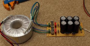
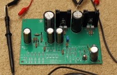
Just finished the outboard PSU for the Pearl as well as populating the onboard regulators. I've used a 28v transformer with CRCRC filtering (10,000uF and 10R). The outboard PSU provide 39.2VDC to the onboard regulators, which provide 24.3VDC for the rest of the board.
Everything looks OK, but I'm thinking +/-39.2V is a bit high for the 7824/7924 which specify a maximum input voltage of 40v. Should I put in a few diodes to drop the voltage down a bit?
I've also never used bleeder resistors in a PSU before. These are 2k2 3w and run at about 58c. The datasheet says they max out at 350c, so I presume they are good at this temp.
Attachments
You could increase the value of the series resistors... not only do you drop a few more volts, but the filtering is increased by a significant amount.
Pass DIY Addict
Joined 2000
Paid Member
I was thinking of trying so 20r resistors that I have, but was wondering if they would do any good to bring down voltage since the power supply measures 39.2v all of the way through. It seems that the Pearl does not draw enough current to really make the resistors do much to the voltage.
I'll stick a set of resistors directly after the rectifiers to see how this affects the voltage.
I'll stick a set of resistors directly after the rectifiers to see how this affects the voltage.
Series resistors after the rectifier will make a noticable drop. It should work great! Also make sure you use large dissipation resistors, as the AC component that they see is quite large.
If you can take a scope shot of the before and after, that would be cool... filtering like that is extremely effective. (As it's so lossy.)
If you can take a scope shot of the before and after, that would be cool... filtering like that is extremely effective. (As it's so lossy.)
Pass DIY Addict
Joined 2000
Paid Member
Did some measurements with various amounts of resistance placed in various places in the PSU. I'm using a 28v transformer, MUR820 diodes, 0.22uF film cap, 2k2 bleeder resistors, followed by CRCRC made of 10,000uF and 10R 3w resistors. This configuration provides 40.0vDC on the PSU output
To make any real impact on the output, additional resistance needs to either be directly after the rectifier or at the output from the PSU, after the last cap. Also, to make any real impact, the resistance needs to be rather large.
Placing a 20R 5w resistor after the rectifier provides 38.2v out from the PSU, which drops to 37.5v when one Pearl channel board is connected to the PSU. Changing this to 40R after the rectifier provides 37.0v out from the PSU, which drops to about 36.0V with one Pearl channel board connected to the PSU. Both of these changes are a little boring - not much happens here.
If I put a 1kohm 1/4w resistor on the output of the stock configured PSU, it drops the output voltage down to 32.8v with one Pearl channel driven. I figured this largely killed the value of all of the capacitance in the PSU.
Things got interesting, though, when I put a larger resistor after the rectifier. I tried a 390R 3w resistor and this dropped the PSU output to 23.8v - too low to be useful.
So, I paralleled two 390R 3w resistors (~200R) and this provided 26.3v DC on the PSU output when driving both Pearl boards, still enough to drive the output of the Pearl regulator to full power at 24.3v.
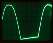
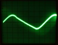
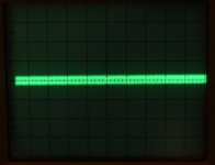
Three images from my scope are below. The first one is taken directly after the rectifier and before the paralleled 390R 3w resistors. This shows 5.48v AC ripple (1v/division) The second image is taken directly after the paralleled 390R resistors and shows 3.6mV (2mV/division) of AC ripple - quite a reduction in ripple! The final image is from the output of the PSU after the last cap. Scope is set to 2mV/division and shows less than 0.1mV ripple.
I will try one more configuration with ~100-120R after the rectifier. I'd like to give the onboard regulator just a bit more headroom.
To make any real impact on the output, additional resistance needs to either be directly after the rectifier or at the output from the PSU, after the last cap. Also, to make any real impact, the resistance needs to be rather large.
Placing a 20R 5w resistor after the rectifier provides 38.2v out from the PSU, which drops to 37.5v when one Pearl channel board is connected to the PSU. Changing this to 40R after the rectifier provides 37.0v out from the PSU, which drops to about 36.0V with one Pearl channel board connected to the PSU. Both of these changes are a little boring - not much happens here.
If I put a 1kohm 1/4w resistor on the output of the stock configured PSU, it drops the output voltage down to 32.8v with one Pearl channel driven. I figured this largely killed the value of all of the capacitance in the PSU.
Things got interesting, though, when I put a larger resistor after the rectifier. I tried a 390R 3w resistor and this dropped the PSU output to 23.8v - too low to be useful.
So, I paralleled two 390R 3w resistors (~200R) and this provided 26.3v DC on the PSU output when driving both Pearl boards, still enough to drive the output of the Pearl regulator to full power at 24.3v.
Three images from my scope are below. The first one is taken directly after the rectifier and before the paralleled 390R 3w resistors. This shows 5.48v AC ripple (1v/division) The second image is taken directly after the paralleled 390R resistors and shows 3.6mV (2mV/division) of AC ripple - quite a reduction in ripple! The final image is from the output of the PSU after the last cap. Scope is set to 2mV/division and shows less than 0.1mV ripple.
I will try one more configuration with ~100-120R after the rectifier. I'd like to give the onboard regulator just a bit more headroom.
Attachments
Rather than resistances use some emitter follower transistors TIP35/36 with base voltage controlled through variable resistances. Look out for capacitance multiplier circuits for more information.
Sent from my iPad using Tapatalk
Sent from my iPad using Tapatalk
I ordered the boards and bought a transformer. I guess I'm committed now.
(Or perhaps I should be committed. 🙂 )
Dennis
(Or perhaps I should be committed. 🙂 )
Dennis
Pass DIY Addict
Joined 2000
Paid Member
Welcome to it, Dennis! Just finished populating my boards a day or so ago and a new chassis in on its way...
You'll love it!!
Yes! Get on it.dont piddle around for 5 years like I did. It is one of the largest jumps in performance I have had. Seriously!
Thanks! I'm very excited about this, though I really need to finish the
BA3 preamp first. 🙂 The parts collection process beings...
I'm using an Ortofon 2m bronze:
Ortofon - 2M Bronze
Would you recommend building the Pearl 2 as-is or try to lower the gain?
Cheers,
Dennis
BA3 preamp first. 🙂 The parts collection process beings...
I'm using an Ortofon 2m bronze:
Ortofon - 2M Bronze
Would you recommend building the Pearl 2 as-is or try to lower the gain?
Cheers,
Dennis
Pass DIY Addict
Joined 2000
Paid Member
Dennis, looks like your cart has the same output, 5mV, as the one I've chosen (audio technica AT150). I asked a similar questipn and was told to just build it stock. It will likely be another 2-3 weeks before I'm ready for a listen, so I won't have any personal commentary until then.
Just build it stock. Only increase the gain if needed.
(And it won't be needed with that cartridge.)
(And it won't be needed with that cartridge.)
Just build it stock. Only increase the gain if needed.
(And it won't be needed with that cartridge.)
I built mine stock. Has worked fine with Ortofon Super OM 30, Shure V15 Vxmr, soon to try my SAE 1000 LT.
It also worked fine (with BA-3 preamp) using a Denon 103, which is a fairly low output moving coil, just had to crank the volume a little harder. Another vote for stock unless you need MORE gain.
Russellc
- Home
- Amplifiers
- Pass Labs
- Building a Pearl 2