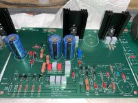
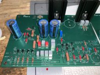
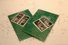
Almost finished repopulating the Pearl Boards, forgot to order the 221 ohm resistors I wanted and some standoffs for Rx and Cx. I will need to build little shelf’s on the chassis sides for C1 and C26.
B1 is completely redone besides the volume and switch wiring.
Probably tomorrow I will look at getting the power box stated. I will need to do a dry fit for everything in it before getting the components in permanently.
B1 is completely redone besides the volume and switch wiring.
Probably tomorrow I will look at getting the power box stated. I will need to do a dry fit for everything in it before getting the components in permanently.
Attachments
Russellc,
I have a few question’s for you if you do not mind.
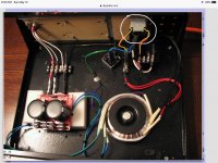
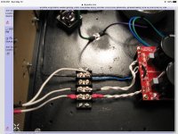
In the first attachment:
What is the device circled in white?
It looks like main power coming in but what are the two red wires that I marked in yellow.
Same goes for the wire I marked blue. I believe it is the ground from the main power but not know what that little device is with the two red wires on I just want to be sure.
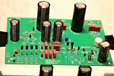
On the second attachment:
What wires are those that I put a blue line next to? It almost looks like they go under the board but am not sure.
And just a general question.
The secondaries coming off of the transformer and go under the power board, are both the blue and green wires getting hooked up to the board under there?
Thanks, James
I have a few question’s for you if you do not mind.
In the first attachment:
What is the device circled in white?
It looks like main power coming in but what are the two red wires that I marked in yellow.
Same goes for the wire I marked blue. I believe it is the ground from the main power but not know what that little device is with the two red wires on I just want to be sure.
On the second attachment:
What wires are those that I put a blue line next to? It almost looks like they go under the board but am not sure.
And just a general question.
The secondaries coming off of the transformer and go under the power board, are both the blue and green wires getting hooked up to the board under there?
Thanks, James
Attachments
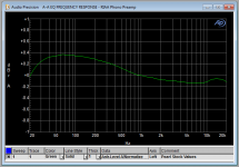
The Pearl will easily overload with MM cartridge.
Here are the correct RIAA values -- :
I am wondering if anyone made the changes to the values of the components listed in this post? Thanks.
I have attached the screenshot from the post showing the new values.
Attachments

Last edited:
Can someone please show me where the .22uf film snubber caps are installed? The reason I ask is I will not be using the same power supply setup shown by 6L6 in the first post.
I will only be using one 35 amp bridge where his drawing shows two of them. Thanks.
I will only be using one 35 amp bridge where his drawing shows two of them. Thanks.
Last edited:
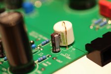
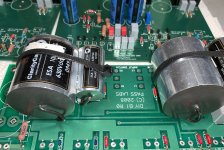
Looks very nice, like that Mundoff. What is the manufacturer of the red caps.
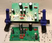
I have the same little PCB holder and love that little thing.
I have the same little PCB holder and love that little thing.
I am wondering if anyone made the changes to the values of the components listed in this post? Thanks.
I have attached the screenshot from the post showing the new values.
Yes, I did. I made some (many) modifications to my Pearl 2 (will report later), one of them was changing the values of the RIAA. Because I'm also in the process of installing a new cartridge, I have not had a chance to listen to the result of all the modifications.
I am wondering if anyone made the changes to the values of the components listed in this post? Thanks.
I have attached the screenshot from the post showing the new values.
These were posted before, but to spare y'all having to parse a thousand posts:
Attachments
These were posted before, but to spare y'all having to parse a thousand posts:
Thank you very much for the post and reply. I will show my ignorance here and let you know the last two screenshots do not point me in a direction for component changes where as the post of yours that I quoted does have gym on it valuable information in there.
So far I found the below information you had posted which, if I read everything in context, would make these boards more MM friendly.
R9 - 255 ohms
R12 - 6.81K
R2 - 100K||1K
C10 - .110uf
C12 - .1uf
C16 - .1uf
C20 - .32uf
Thanks, James
Yes, I did. I made some (many) modifications to my Pearl 2 (will report later), one of them was changing the values of the RIAA. Because I'm also in the process of installing a new cartridge, I have not had a chance to listen to the result of all the modifications.
Wellerman,
That would be greatly appreciated if you can let me see the changes you made when you have the time.
Thanks, James
Don't know if you're supposed to change R9, I kept it at 499. Others might know. You can also lower gain by increasing R14. R11 = 6k81 just like the original schematic. For RIAA change R12 to 990 (100K||1k, but Vishay also has a 990 in their CMF series). C10+C11+C14 = 0.11uF (so you could just leave out C10 or C11 from the original schematic). C17+C18+C19+C20 = 0.32uF (easiest to choose C20 = 0.02 or 0.022uF). C12 + C16 can be increased in value if you want less subsonic rolloff.
Thank you very much.
I will to order those components which is not a problem since the boards are not mounted as of yet.
If I read jackinnj’s screenshot and post information I have above, it looks like he is suggesting to change R9 to 250 ohms.
So I will probably do that also.
I will to order those components which is not a problem since the boards are not mounted as of yet.
If I read jackinnj’s screenshot and post information I have above, it looks like he is suggesting to change R9 to 250 ohms.
So I will probably do that also.
Just to make sure: by Cx+Cy+Cz = xx uF I mean the combined value of those capacitors should be xx uF (not: each of those should be that value).
Just to make sure: by Cx+Cy+Cz = xx uF I mean the combined value of those capacitors should be xx uF (not: each of those should be that value).
I am following you.
Thanks for making sure I am understanding you though!
James
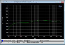
Jackinnj,These were posted before, but to spare y'all having to parse a thousand posts:
Would you be so kind as to let people like me know components were changed and to what values to get the second curve in your post.
It would be greatly appreciated.
- Home
- Amplifiers
- Pass Labs
- Building a Pearl 2