Thanks! I'm very excited about this, though I really need to finish the
BA3 preamp first. 🙂 The parts collection process beings...
I'm using an Ortofon 2m bronze:
Ortofon - 2M Bronze
Would you recommend building the Pearl 2 as-is or try to lower the gain?
Cheers,
Dennis
You are going to love that preamp as well, although I have a small amount of popping when changing inputs, and a slight hum if I select an input with nothing on it. Shorting jacks work here but I would like to silence it completely. That may take different switching? Using tubecad.com selector switch. would also like to eliminate hum without resorting to shorting plugs...seems like that shouldnt be that difficult, but I will have to ask more questions!
Russellc
Gentlemen,
Thanks again. My concern was the possibility of too much gain and
overloading the phono stage. But I will stick with the stock build.
What caps are you using for C1, C26? I read in a post that the silkscreen
is 24mm in diameter an am wondering if I need to go with a 22mm cap or
if I might get away with a 25mm one?
Cheers,
Dennis
According to Wayne, overloading the stock input stages takes a cartridge capable of outputting in excess of 10mV!
😱😱😱
Probably not going to find anything that is capable of that.
😱😱😱
Probably not going to find anything that is capable of that.
Just build it stock. Only increase the gain if needed.
(And it won't be needed with that cartridge.)
Uuuuhhh, bad advice -- the RIAA values need tweaking.
According to Wayne, overloading the stock input stages takes a cartridge capable of outputting in excess of 10mV!
😱😱😱
Probably not going to find anything that is capable of that.
That's not correct either -- a 5mV cartridge at 1kHz will put out 50mV @10kHz.
All I can say is, as "imperfect" as it may be, it sounds wonderful, and it replaced one that wasnt exactly crappy....just saying.
If you think there are improvements, lets hear about it so they can be put to the test!🙂
Russellc
If you think there are improvements, lets hear about it so they can be put to the test!🙂
Russellc
Pass DIY Addict
Joined 2000
Paid Member
Jack: please share your suggested tweaks to the RIAA network.
Dennis: these fit: UVY1H103MRD Nichicon | Mouser
Dennis: these fit: UVY1H103MRD Nichicon | Mouser
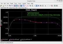
Jackinnj, Can you clarify the following, You indicated R12 = 6.81k, and R2 = 100k||1k, in the Pearl 2 schematic, i.e. Fig 2. R12 = 909ohm and would like to point out there is a R11 = 6.81k in the RIAA network that suspiciously has the same value as your R12. R2 on the other hand is 10ohm input resistor (and is parallel to R1 another 10ohm resistor) for the 7824 regulator. 100k||1k just reduce effective R to 999 ohm or 1% change on the other if u meant to type 10k||1k that would equal 909, the current value of R12 in Pearl 2 schematic.
Alex
C14+C10+C11 = 0.12uF, you indicated C10 = 0.11uF and C17+C18+C19+C20 = 0.333uF while you indicated C20 = 0.32uF. Are u saying I just need to remove C11 = 0.01uF and change C20 = 0.02uF.
Alex
C14+C10+C11 = 0.12uF, you indicated C10 = 0.11uF and C17+C18+C19+C20 = 0.333uF while you indicated C20 = 0.32uF. Are u saying I just need to remove C11 = 0.01uF and change C20 = 0.02uF.
Jack, is that measured or simulated?
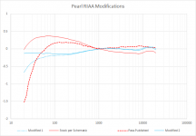
Here are the actual data -- including the numbers from the chart in the PASSDIY article, obtained with CurveCaptor. I went down this route since the simulation first indicated that Wayne's component values weren't quite correct. The data compares a STOCK Pearl 2 built with close tolerance components, to the published design, and the one I built with values closely approximating those obtained from the Lipshitz paper.
Attachments
C14+C10+C11 = 0.12uF, you indicated C10 = 0.11uF and C17+C18+C19+C20 = 0.333uF while you indicated C20 = 0.32uF. Are u saying I just need to remove C11 = 0.01uF and change C20 = 0.02uF.
Modified 2 replaces the 0.1+0.1uF coupling caps with 0.1+0.47uF
You also get a good resistor match with 100k in parallel with 1k
Pass DIY Addict
Joined 2000
Paid Member
Jack, thanks for sharing the RIAA details. I want to give mine a listen before I make any changes..
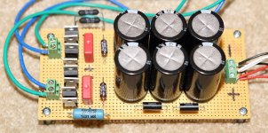
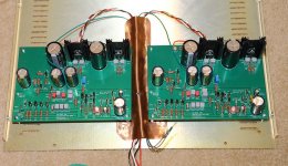
I've made some progress on my Pearl build. The boards are completed and mounted to the bottom of the chassis. I used an old copper sheet to shield the power cords from the rest of the circuit. Don't know if this makes any real difference, but thought it certainly couldn't hurt.
After running both boards (now completed, not just the regulator sections), the draw from the PSU is greater, which caused my voltage to drop so I altered my resistors again. I ended up inserting parallel 91R 3w in the negative rail and a 20R 5w on the positive rail (which seems to have greater current draw) directly after the rectifiers. Using different resistance in each rail allows the PSU outputs to be the same at +/- 30.7V. If I bypass theses resistors, the PSU output jumps to 37.2v, so they drop a good bit of voltage and provide a bit of a "soft start" for the circuit to boot - it takes about 10-15 to come up to full power.
The output offset is a bit strange, though. Without anything on the inputs (just open), I can adjust P1 for 0-2mV on the output terminals which stays pretty steady, but this leaves as much as 20-30mv on the P1 test pad as marked on the board. The voltage on the output pads seem to be pretty stable, but the P1 test pad dances around a bit. Is this pretty normal? Is it because I haven't shorted the inputs?
I need a few more parts to arrive tomorrow before I can complete the Pearl chassis. Starting to wish Mouser offered "Mouser Prime" shipping 😀
Attachments
Jack, thanks for sharing the RIAA details. I want to give mine a listen before I make any changes..
I've made some progress on my Pearl build. The boards are completed and mounted to the bottom of the chassis. I used an old copper sheet to shield the power cords from the rest of the circuit. Don't know if this makes any real difference, but thought it certainly couldn't hurt.
After running both boards (now completed, not just the regulator sections), the draw from the PSU is greater, which caused my voltage to drop so I altered my resistors again. I ended up inserting parallel 91R 3w in the negative rail and a 20R 5w on the positive rail (which seems to have greater current draw) directly after the rectifiers. Using different resistance in each rail allows the PSU outputs to be the same at +/- 30.7V. If I bypass theses resistors, the PSU output jumps to 37.2v, so they drop a good bit of voltage and provide a bit of a "soft start" for the circuit to boot - it takes about 10-15 to come up to full power.
The output offset is a bit strange, though. Without anything on the inputs (just open), I can adjust P1 for 0-2mV on the output terminals which stays pretty steady, but this leaves as much as 20-30mv on the P1 test pad as marked on the board. The voltage on the output pads seem to be pretty stable, but the P1 test pad dances around a bit. Is this pretty normal? Is it because I haven't shorted the inputs?
I need a few more parts to arrive tomorrow before I can complete the Pearl chassis. Starting to wish Mouser offered "Mouser Prime" shipping 😀
Yes, I fiddled and faddled with mine on and on. Even breathing on them with the top on through the vents made stuff silly. Finally I put a small towel over the vents and listened to it....havent needed to adjust a thing! Sounds great!
Pass DIY Addict
Joined 2000
Paid Member
I've always experienced these offset adjustments to be a bit finicky. Both channels are very sensitive to adjustment - small adjustments move offset by relatively large amounts. One channel adjusts smoothly and predictably while the other channel is a bit twitchy. On the twitchy channel, a slight adjustment leads to more significant swings in offset, from positive to negative and back again until it settles. I'm wondering if I have a cold solder joint on the pot. I'll have to reflow it.
Do your LEDs blink at all as the boards start up? The nature of my PSU (added resistance following the rectifier) makes it somewhat softstart in nature. So, the LEDs are initially off for the first second or two after receiving power, then they start to glow, blink off for a fraction of a second, then come back on and slowly get brighter as the power supply hits full power.
Do your LEDs blink at all as the boards start up? The nature of my PSU (added resistance following the rectifier) makes it somewhat softstart in nature. So, the LEDs are initially off for the first second or two after receiving power, then they start to glow, blink off for a fraction of a second, then come back on and slowly get brighter as the power supply hits full power.
I've always experienced these offset adjustments to be a bit finicky. Both channels are very sensitive to adjustment - small adjustments move offset by relatively large amounts. One channel adjusts smoothly and predictably while the other channel is a bit twitchy. On the twitchy channel, a slight adjustment leads to more significant swings in offset, from positive to negative and back again until it settles. I'm wondering if I have a cold solder joint on the pot. I'll have to reflow it.
Do your LEDs blink at all as the boards start up? The nature of my PSU (added resistance following the rectifier) makes it somewhat softstart in nature. So, the LEDs are initially off for the first second or two after receiving power, then they start to glow, blink off for a fraction of a second, then come back on and slowly get brighter as the power supply hits full power.
Well I do not have a slow start on mine, its just wired like the schematic. Upon turn on the power supply led comes on steady, I will have a look at the phono boards when I get home, but I remember them just coming on. Let me double check this eve.
Well, I picked up the PCBs from the post office today.
I'm thinking of getting a couple of these cheap and cheerful Hammond boxes:
1441-32BK3 Hammond Manufacturing | Mouser
I saw a mention earlier in this thread about a cardas ground post. Is this the one?
Take Five Audio - Canada's Online Source For DIY Audio, Parts and Accessories - Cardas GRND Ground Post
Cheers,
Dennis
- Home
- Amplifiers
- Pass Labs
- Building a Pearl 2