Hi all,
For those concerned about Subbu DAC PSU, Have a look there :
http://www.diyaudio.com/forums/solid-state/253390-experimentations-regulators-5.html#post3894560
Kudos to "Moderator Emeritus" Jean Paul for his design 😎
Regards
Phil
For those concerned about Subbu DAC PSU, Have a look there :
http://www.diyaudio.com/forums/solid-state/253390-experimentations-regulators-5.html#post3894560
Kudos to "Moderator Emeritus" Jean Paul for his design 😎
Regards
Phil
Last edited:
What I will do are:
1. Remove L1 and measure. If the continuity is gone, then you know the issue is from the down stream of L1. If situation doesn't change, then
2. Remove L2 and measure. If the continuity is gone, then the issue is from the down stream of L2. If nothing is changed, then you can focus on the circuitry on WM side.
This approach should help narrowing down what to check next.
Good luck!!
Hi pchw
You're awfully right !
Removing L1 and then L2 will show if WM8804 section is concerned or not.
Checked all MIC's with a 8x magnifier and tested them with buzzer function. All have continuity which cannot be true. None of the parts are looking abused or burned. All tant caps 4.7uF before the regs buzzed (and were removed probably unnessecarily), all tant caps AFTER the regs are fine. To continue the story I removed U3 -> pads underneath clean and no bridges. The desoldered U3 on my desk has no continuity between pin 1 and 2... so no short here although it buzzed before. X1 is removed, no traces of solder. I am at a loss.
What if shorted at U4, U5 and U6? Power tee off at pin 1 of X1, power route to L1, L2 for U3 & U4 respectively. I see L1 still in the board but not sure about L2. If short somewhere at U4 continuity will present at X1, assumed L2 not remove from the board. Try remove L2 and re-check continuity at X1 since you already have U3 removed.
Sidney
What I will do are:
1. Remove L1 and measure. If the continuity is gone, then you know the issue is from the down stream of L1. If situation doesn't change, then
2. Remove L2 and measure. If the continuity is gone, then the issue is from the down stream of L2. If nothing is changed, then you can focus on the circuitry on WM side.
This approach should help narrowing down what to check next.
Good luck!!
Similar problem Thecoolestone had faced. Caps before U regs buzzing and after not buzzing. Problem was U regs only.
I would remove U3, U4, U5 and U6, clean the pads properly and I think buzz will be gone. Try it..
Last edited:
Fixed
Dear Sydney, Phil, JP, Darshanjoshi, Fred, TheCoolestOne and all,
thanks a lot for helping out and encouraging me, but you were all wrong 😉.
After the board kept buzzing at me with ZERO resistance I began suspecting a short in the board somewhere, and that's what it was!
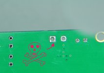
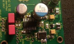
Inspecting every mm of the board with the 8x lens I found a tiny copper bridge at the + terminal of X1 --> see pic. Once removed I hopefully have
a working board and just need to repopulate the desoldered parts. Anyone wanting to donate some 4,7uF Tantalum caps (the yellow bricks) is very welcome. 🙂
Korben69 also indicated to have some parts left that he can contribute.
But first... off into a short Easter holiday in my hometown!
Thanks guys, you all helped me with your persistance!
😀
PS. Of course I'll pay for all parts!
Dear Sydney, Phil, JP, Darshanjoshi, Fred, TheCoolestOne and all,
thanks a lot for helping out and encouraging me, but you were all wrong 😉.
After the board kept buzzing at me with ZERO resistance I began suspecting a short in the board somewhere, and that's what it was!
Inspecting every mm of the board with the 8x lens I found a tiny copper bridge at the + terminal of X1 --> see pic. Once removed I hopefully have
a working board and just need to repopulate the desoldered parts. Anyone wanting to donate some 4,7uF Tantalum caps (the yellow bricks) is very welcome. 🙂
Korben69 also indicated to have some parts left that he can contribute.
But first... off into a short Easter holiday in my hometown!
Thanks guys, you all helped me with your persistance!
😀
PS. Of course I'll pay for all parts!
Attachments
Last edited:

Dear Sydney, Phil, JP, Darshanjoshi, Fred, TheCoolestOne and all,
thanks a lot for helping out and encouraging me, but you were all wrong 😉.
I am sure we are all glad to be wrong 😀. Hopefully your DAC works this time.
hI,
I believe I had a short on the ES9023 on my second subbu board !
Values are strange : pin 1 : 3.53V , Pin 2 : 0V... soldering was checked and applyed again (no dry soldering & no shorts on the pins)
Values from the reg are goods but not the first time I connect the board... always this story of dry solderind... Did it break the ES9023 the first time?
Values fro WM8804 are strange : no shorts, I change twice the chip and values are the same and bad : pin 9 : 0 v but pin 10 ok with 3.23.. pin 7: 0v instead 3.3 ????
Does a broken ES9023 can change the value of the WM8804 pins ?
All was checked with magnifying glass, buzzer & Volt value. I found the swiss distributor given by a fellow and bought 1 ES9023 for 1.7 euros (no postal shippment... hope I didn't made an error about the shipment...).
Do you believe it's the ES90233P ? How to get it off from the board without damaging the board (3 pins- the ones not connected...lucky I am- were broke when WM8804 was removed...) I don't want make more damage with removing the ES9023 : wall paper hot air remover like some do with computer boards on Youtube ? Or carrefully pin by pin with soldering ?
Eldam,Do you believe it's the ES90233P?
It would be helpful if you could provide a few high quality pictures and a table showing the voltages for the WM8804 and ES9023. Earlier in this thread there were tables published showing "good" values and also the values when some other people had trouble. Please compare your DAC to those tables and then you can start to isolate what might be the problem.
My guess is that the trouble is not the WM8804 or the ES9023 unless there is a problem with shorts or unsoldered pins. But it sounds like you checked for that already. More likely there is a problem with one of the clocks or other support circuits.
---Gary
Thank you Garry,
I have been taking the WM8804 value again when i saw than voltage was moving on some pins like with caps. With the magnfying,glass the soldering seemed good but i soldered once more with more flux and the magnyfing glass again.
Measurement is better after that : ES9023 values are good now, but as the pcb were broken below the WM88004 (when I put a new one) maybe have I a problem. All the strange values are now correct (Korben photograph with values ) but:
- pin 17: 0.02 (instead: 0.03) but maybe it's correct as it's close
- pin 16: 0.98 (instead: 1.65) : does it go to GND ?
Have to sat than the crystal is with 18 pf (it's not an FOx but a TCX 10 ppm maid for 18 pf colpitt load)
in fact the problem begann when I tryed to sold the chips with an Antex 18 W for smd : the bigger soldering iron was safer with more flux than the little Antex (not hot enough with silver soldering). What is incredible for me is than I'am enable to see with eyes when a soldering is dry... and with the chips I'm scared to go above 350° with the soldering iron !
Is the pin 16 value a problem ?
I have been taking the WM8804 value again when i saw than voltage was moving on some pins like with caps. With the magnfying,glass the soldering seemed good but i soldered once more with more flux and the magnyfing glass again.
Measurement is better after that : ES9023 values are good now, but as the pcb were broken below the WM88004 (when I put a new one) maybe have I a problem. All the strange values are now correct (Korben photograph with values
) but:- pin 17: 0.02 (instead: 0.03) but maybe it's correct as it's close
- pin 16: 0.98 (instead: 1.65) : does it go to GND ?
Have to sat than the crystal is with 18 pf (it's not an FOx but a TCX 10 ppm maid for 18 pf colpitt load)
in fact the problem begann when I tryed to sold the chips with an Antex 18 W for smd : the bigger soldering iron was safer with more flux than the little Antex (not hot enough with silver soldering). What is incredible for me is than I'am enable to see with eyes when a soldering is dry... and with the chips I'm scared to go above 350° with the soldering iron !
Is the pin 16 value a problem ?
Attachments
My understanging is WM8804 pin 16 is not connected (MLCK not used in this design) but I don't know if the volt value at the pin is important as an indicator of the rest of the internal circuit health?.
Anyway i will try it tomorow!
Anyway i will try it tomorow!
My understanging is WM8804 pin 16 is not connected (MLCK not used in this design) but I don't know if the volt value at the pin is important as an indicator of the rest of the internal circuit health?.
Anyway i will try it tomorow!
I think the values are important not in the context that it is passing data to this dac but in the context that if values are correct DAC will work.
I had similar problems with WM. Resoldering of WM eventually solved the problem specially Pin 1,2,3,4,20.
Because they are more involved (datasheet). Pin 16 is not needed HERE but maybe you're right : if value is good (Korben69 picture with values) reflect the state of the system... just a faith, I don't know. But I will tell you tomorow after a hearing test...

Thank you Garry,
I have been taking the WM8804 value again when i saw than voltage was moving on some pins like with caps. With the magnfying,glass the soldering seemed good but i soldered once more with more flux and the magnyfing glass again.
Measurement is better after that : ES9023 values are good now, but as the pcb were broken below the WM88004 (when I put a new one) maybe have I a problem. All the strange values are now correct (Korben photograph with values
- pin 17: 0.02 (instead: 0.03) but maybe it's correct as it's close
- pin 16: 0.98 (instead: 1.65) : does it go to GND ?
Have to sat than the crystal is with 18 pf (it's not an FOx but a TCX 10 ppm maid for 18 pf colpitt load)
in fact the problem begann when I tryed to sold the chips with an Antex 18 W for smd : the bigger soldering iron was safer with more flux than the little Antex (not hot enough with silver soldering). What is incredible for me is than I'am enable to see with eyes when a soldering is dry... and with the chips I'm scared to go above 350° with the soldering iron !
Is the pin 16 value a problem ?
Your soldering obviously is a problem. Please take that skill to a next level Eldam. The V3 (and every other serious audio device) deserves it. Do you know how much cold joints can affect sound quality ?
First things first...
You can go on and on about different caps but the basics are way more important. A good joint on a BOM part could sound better than a cold joint on a supposedly better part 😉 Please use good tools and materials and train your skills. Good 60/40 solder and a good soldering tool like Weller WTCP-S (if you're on a budget) and some hours practicing are what you need...
And clean the board afterwards !
Last edited:
thank you for the advices JP, positives critics help.
Unhappily for an expensive soldering iron... this is not the good moment for me as a good station is near the price of a washing machine. But it will come.
So : You mean to avoid 96 SN /4 AG soldering (need >350°) for a more classical!
What is the current temperature needed and how to see how a cold joints are : mat and not brigthy ? This is it ? I always scare to burn the small devices because when I read the datasheet, I often see : small 250° for a couple of seconds ....
In the photograps you saw I tired to use small quantity of soldering... But the brand new antex 18W 20 euros for smd was bad for that with the 96/4ag... I needed to use my chineese thermostat station at 35O° ! But you mean that the soldering are bad ? Is it because not brighty or too much soldering or not clean (all of that) ?
I hope I'm not the worst diyer of the V3....Dont forgett it was for me and for more than you think a first time with smd soldering.
I don't forgett myself than the Subbu gave to me a good occasion and will to test... beginners often need encouragements but concrete advice yet... or th eproject stay "not for the beginners"... what is a pity according my self vision of music, DIY and general sharing.
Thank you, i surmise if you wrote this, thisis because you have faith to motived beginners.
Last edited:
AFAIK it was repeated n times that good standard leaded solder should be used. You should avoid lead-free stuff like the plague. Don't think it is better because of the silver or because the world will be a better place. It won't. Admitted: you must not eat 60/40 soldered stuff. 60/40 soldered stuff keeps working contrary to lead-free soldered stuff. Joints look and are better and your parts don't get killed as easily as with the lead-free stuff. You should talk to LCD/Plasma TV repair guys to get even sharper opinions....
Spent 75 to 100 Euro on a used but good functioning Weller WTCP-S, 7 Euro for a PT-D tip number 7 and 10 Euro on a spool of 0.7 mm (or thinner) Fluitin 60/40 or 60/38/2 and you are a winner. If you are on a shoestring just buy the solder and use the Antex. If it is adjustable 275 to 350 degrees should be OK. Try what works best for you. Higher temp works OK if you can solder quickly.
Please don't start talking details when the basics are not met. When the basics are not met ? -> Don't start the project till they are. Count from 1 to hundred and not from hundred to 1.
Last edited:
Here ? In the pre advices ? Where ? I miss that.
You are a little hard. I surmise experience needs practice and practice has to start somewhere... You seem not like "beginners" with your projects but seem more open when it's for a better global audio quality for everybody... sometimes I don't understand some apories from you. But I can tell you I'm certainly more happy with my Subbu that without. A positiv point no ?
About the tweakings: I am always prudent and humble witrh claiming it's not to be better but to setup with its own system and flavors... cause no universal taste and hifi system...flat tonal systeme and devices don't exist and I found myself caps like PS are a good way for those setups. That's all. Sorry it's borring you or that you are suspicious about my humble tests with some caps, it's not I want to do better it's just I'm a motived guy. (but agree which need advices in this hobby to involve his knowledge and skill...more than general recriminations or childish remarks). Finally I learn a lot with your smart design...and this not a waste according to me.
Last edited:
- Home
- Source & Line
- Digital Line Level
- Build thread - building the Subbu DAC V3 SE