Take your time, use a good magnifier glass, leaded solder, flux, and train yourself on the Old DAC board 🙂I am using 60/40 solder of 0.5mm. -> Prefer leaded Solder
I am having trouble with the solder iron tip. -> Train yourself using old PC parts 😉
For MIC5205 regs you don't need to carry solder. Just use flux.
All the best
Regards
Phil
I am using 60/40 solder of 0.5mm. I am having trouble with the solder iron tip. For U1, U2 and the other U regs should I carry a little solder on the tip or should I just solder the normal way of letting the solder flow from the wire to the iron. The reason I ask this is that the thin tip I use (see the pic I have posted earlier) is unable to carry enough solder on the tip and I end up adding more solder than required.
Try to heat the parts lead wire and add solder wire very shortly after.
Don't carry solder on the tip of the soldering iron, it is plain wrong to do so.
Take your time, use a good magnifier glass, leaded solder, flux, and train yourself on the Old DAC board 🙂
All the best
Regards
Phil
Will practice on the old board for sure till the new one arrives.
Try to heat the parts lead wire and add solder wire very shortly after.
Don't carry solder on the tip of the soldering iron, it is plain wrong to do so.
Will try this method. The WM8804 is the only problem I can see as distance between the pins is very less. I did struggle on this.
The WM8804 is the only problem I can see as distance between the pins is very less.
Use Sodler Braid and SMD Flux, it solves all your troubles as a wizard 🙂
Regards
Phil
1. Buy better branded solder 60/40 like Fluitin.
2. Solder all pins at once with plenty solder and do this quick and painless. This will also fill the space between the pins and make shorts. Don't be afraid, this will be OK.
3. Now heat a piece of desolder braid and move this over the pins in a brushing movement with the soldering iron with only a light pressure (don't push).
4. Carefully check if there are no solder bridges between pins anymore. Rework if necessary.
5. Clean the board/chip with isopropyl alcohol 99%.
This will only work when the braid is hot enough! The braid will suck all excessive solder and bobs yer uncle ! After a while you will get the hang of it. It is experience you need and for that you need practice.
Last edited:
I am using 60/40 solder of 0.5mm. I am having trouble with the solder iron tip. For U1, U2 and the other U regs should I carry a little solder on the tip or should I just solder the normal way of letting the solder flow from the wire to the iron. The reason I ask this is that the thin tip I use (see the pic I have posted earlier) is unable to carry enough solder on the tip and I end up adding more solder than required.
Hi CoolestOne,
I learned a lot of soldering tricks and tips from these videos:
EEVblog #186 – Soldering Tutorial Part 3 – Surface Mount | EEVblog - The Electronics Engineering Video Blog (surface mount)
EEVblog #434 - SMD Thermal Pad & Drag Soldering Tutorial | EEVblog - The Electronics Engineering Video Blog (surface mount)
EEVblog #180 – Soldering Tutorial Part 1 – Tools | EEVblog - The Electronics Engineering Video Blog
EEVblog #183 – Soldering Tutorial Part 2 | EEVblog - The Electronics Engineering Video Blog
(general electronics soldering)
Dave talks a lot, but if you have the time these are great tutorials.
I also found it very helpful to find an old discarded circuit board with lots of surface mount and practice de-soldering and soldering. Over and over. I used a paint stripping heat gun to remove big chips! 😀 You don't have to worry about damaging things because it's already dead. You can learn how much heat to use and get confident to not damage things.
The other thing I needed was a high power magnifier for inspecting joints afterwards. Joints that look good to your eyes sometimes don't look so good at 10x magnification.
The biggest thing I think is PATIENCE. Plan out what you will do, what angle etc. Maybe only do a few parts then have a rest. I think it took me about 2 weeks to solder my DAC. A few bits here and there. It is good to be fresh. When you start to get tired, you start to rush and mistakes happen.
Phew! Didn't mean to post so long. Good luck! Practice, patience and persistence. Hope you get it working.
Cheers,
Mark
1. Buy better branded solder 60/40 like Fluitin.
2. Solder all pins at once with plenty solder and do this quick and painless. This will also fill the space between the pins and make shorts. Don't be afraid, this will be OK.
3. Now heat a piece of desolder braid and move this over the pins in a brushing movement with the soldering iron with only a light pressure (don't push).
4. Carefully check if there are no solder bridges between pins anymore. Rework if necessary.
5. Clean the board/chip with isopropyl alcohol 99%.
This will only work when the braid is hot enough! The braid will suck all excessive solder and bobs yer uncle ! After a while you will get the hang of it. It is experience you need and for that you need practice.
Thanks for the tips JP. I did try the method you mentioned but somehow my desolder braid isn't adsorbing any excess solder. Maybe my iron tip is too thin to heat it enough and I need to move to a bigger tip to desolder or maybe I am not heating the braid enough. I will practice a bit on the old board before I begin working on the new one.
Thanks for the videos Mark. I had gone thru one of them before starting the build. He made it look so easy in the Video but reality struck me once I started soldering 😀.Hi CoolestOne,
I learned a lot of soldering tricks and tips from these videos:
Mark
I do use a 10x mag to check for joints later. I guess patience is the virtue for such a project 🙂
Buy quality desoldering braid and try to keep it in the package/plastic when not used to avoid corrosion. With a fresh piece it must work. I do this a lot and to me it is the only right method as it is quick and the joints look nice too..
The joints on your PCB look like cold joints or bad solder. I think you should buy good quality 60/40 solder for electronics and good quality desoldering braid first before doing anything. A curry is as good as its ingredients 😉
The joints on your PCB look like cold joints or bad solder. I think you should buy good quality 60/40 solder for electronics and good quality desoldering braid first before doing anything. A curry is as good as its ingredients 😉
Last edited:
TheCoolestOne: Do you have a bigger tips for your soldering iron? Very thin pointed tips lose pretty much heat, so you should have the temperature set higher than with a bigger tip.
My favorite for SMD work is a 2,5 mm wide chisel tip. It gives nice big contact for the board, so that for example 0804 pads take just a couple seconds to heat up. Then as said using leaded solder in a thin format gives a good control how much solder there will be in the joint.
My favorite for SMD work is a 2,5 mm wide chisel tip. It gives nice big contact for the board, so that for example 0804 pads take just a couple seconds to heat up. Then as said using leaded solder in a thin format gives a good control how much solder there will be in the joint.
Any expert advice for me?My issue is SPDF signal is grounded and when I remove R2 from circuit,it is not.So what can I do?
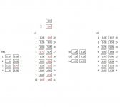
I took readings today again.There is some issue,WM readings show changes.
The table says pin 12 has voltage value 0.036 and Pin13 has 0.83 value,but I am getting interchanged readings.i.e. Pin 12 shows 0.83 and Pin13 as 0.036.
So what can be wrong?
What series are the Nichicon FP capacitors delivered with parts group buy by korben69 for the SUBBU V3 DAC?
On the caps for C2,C3 and C18, I found the following markings:
FP
3XAb
101
16
and
FP
32Ab
101
16
My guess it is 16Volt, 100uf, but i do not understand the 32Ab or 3XAb marking. I cannot find that marking code anywhere in the Nichicon FP cap family documentation.😕
On the caps for C2,C3 and C18, I found the following markings:
FP
3XAb
101
16
and
FP
32Ab
101
16
My guess it is 16Volt, 100uf, but i do not understand the 32Ab or 3XAb marking. I cannot find that marking code anywhere in the Nichicon FP cap family documentation.😕
Last edited:
Hello All
I completed my build but to my dissapointment it is not working.
My PSU is showing correct 5.0v
Before soldering L3, 4, 5, 6, i had checked and all the values were correct.
All parts were used given by Korben except C17 and C22.
Attached is the picture of my build. Can someone suggest how can i proceed further.
For testing purpose i have used cat5 cables for spdif in and analog out.
Thanks
Some of your solder joints are looking a bit dubious (cold) and you have used way too much solder on some of them.
I would check the voltages around the two IC's... someone has posted nice tables with the voltages earlier in the thread.
I suspect that you have power at the regs but something down the way is messed up.
Also C22 is damn close to some solder pads nearby and could be making unwanted contact...
I have lifted the C22 Caps but no output as yet. Hence C22 seems okay.
I have taken some readings at U1 and U2. All readings are taken at 20V DC on DMM.
L1, L2, L3, L4, L5, L6 showings correct Volts.
Also Capacitors before and after U regs are also showing correct Volts.
I can also assure that I did not burn U1 & U2 since I completed them very fast and effortless.
U1 Inputs Values at Position 4 and Position 20 looks off. Could RN1 be problem here? Position 6 at RN1 looks off as compared to other build readings which is Input in Position in 4 of U1.
Can someone please suggest how can I resolve my problem.
Thanks for all your help and Input.
Attachments
Last edited:
I would try to carefully reflow the joints at C4 and on Position 20 and see what happens.Thanks for all your help and Input.
TheCoolestOne: Do you have a bigger tips for your soldering iron? Very thin pointed tips lose pretty much heat, so you should have the temperature set higher than with a bigger tip.
I am using a wider tip for the 0805 and bigger parts. The thin tip was used for the regs and WM8804 and ES9023.
With thin tip temp was set to almost 375 deg centigrade. With thicker tip even 275 degrees was enough.
Sent from my GT-N7100 using Tapatalk 2
I would try to carefully reflow the joints at C4 and on Position 20 and see what happens.
Tried reflowing at C4 and Position 20 but still no luck. In fact also did reflow R2.
Any more suggestions.
Hi
From values posted in #833 I think you're in trouble with all RN1, U1, U2, R4/5/6...
I suggest you to use Flux & Desolder Braid to remove extra solder from those parts.
Don't heat them too long and before, train yourself in this view using old PC parts 😉
You'll see that you need few solder and almost the same amount of Flux to obtain a nice brighfull sodler.
I'll try to post more informations tomorrow.
Regards
Phil
Any DAC pcb's left?
All this modification will eventually have an effect on the board, so I wonder are there any dac pcb's left Subbu?
With regards
Martin
All this modification will eventually have an effect on the board, so I wonder are there any dac pcb's left Subbu?
With regards
Martin
After finally getting mine cased up and listening to it for the last week, I'd like to offer my thoughts on the sound quality of the Subbu DAC.
For context, I have an ODAC, an Eastern Electric MiniMax DAC Plus and an audio-gd reference 7.1 to compare with the Subbu.
I thoroughly enjoy the sound of the Subbu. Personally, I am not one to try to pick the best - I think the concept of best is pure folly. But I can say that I believe the Subbu DAC is a bargain at its price point and I would happily live with it on a long term basis.
Congratulations to all involved.
- Home
- Source & Line
- Digital Line Level
- Build thread - building the Subbu DAC V3 SE