What series are the Nichicon FP capacitors delivered with parts group buy by korben69 for the SUBBU V3 DAC?
On the caps for C2,C3 and C18, I found the following markings:
FP
3XAb
101
16
and
FP
32Ab
101
16
My guess it is 16Volt, 100uf, but i do not understand the 32Ab or 3XAb marking. I cannot find that marking code anywhere in the Nichicon FP cap family documentation.😕
Look at FP datasheet on Mouser... maybe you will find the marking code on a pdf datasheet. ESR family ?
Hi
Parts GB subscribers have received those caps 100uF/16v (C2/3/18) and SAL128 10uF/10v (C8/13/21).
Specs : http://www.mouser.com/ds/2/293/2009fpcap_catalog_r7-3991.pdf
Regards
Phil
Parts GB subscribers have received those caps 100uF/16v (C2/3/18) and SAL128 10uF/10v (C8/13/21).
Specs : http://www.mouser.com/ds/2/293/2009fpcap_catalog_r7-3991.pdf
Regards
Phil
Hi Korben,
The R7 is the one I include for my bench of tweaking test with C18 and/or C22.
This R7 FP cap serie is the lowest avaliable ESR with polymer at 100 uF.
Regards.
The R7 is the one I include for my bench of tweaking test with C18 and/or C22.
This R7 FP cap serie is the lowest avaliable ESR with polymer at 100 uF.
Regards.
After finally getting mine cased up and listening to it for the last week, I'd like to offer my thoughts on the sound quality of the Subbu DAC.
For context, I have an ODAC, an Eastern Electric MiniMax DAC Plus and an audio-gd reference 7.1 to compare with the Subbu.
I thoroughly enjoy the sound of the Subbu. Personally, I am not one to try to pick the best - I think the concept of best is pure folly. But I can say that I believe the Subbu DAC is a bargain at its price point and I would happily live with it on a long term basis.
Congratulations to all involved.
Thanks.
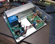
So I've finally completely finished it all.
I find case work a real pain, I'm usually unsatisfied with how my diy gear ends up looking.
I used a hammond 1455 series case with my own front plate. I won't go this way again, as the bottom plate is loose enough to rattle unless you tap the screw holes for larger screws. (PITA).
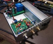
As you can see from the pics, I was paranoid about picking up hum from the mains leads down the side of the case, so I rigged up a steel cover for them.
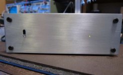
I think it turned out pretty neat. The only bit that bugs me is trying to drill a straight row of ventilation holes. It's probably overkill anyway, but the pass transistor gets reasonably warm, and I like things cool.
Now that I've had a more serious listen, I can say I'm delighted with the sound. It's certainly a step up from the built in decoders in my receiver. 🙂
Parts are all standard GB bom.
Haven't had a chance to take it down to my friend in the hifi shop yet.
Thanks for a great project everyone.
Cheers,
Mark
A few pics:
I find case work a real pain, I'm usually unsatisfied with how my diy gear ends up looking.
I used a hammond 1455 series case with my own front plate. I won't go this way again, as the bottom plate is loose enough to rattle unless you tap the screw holes for larger screws. (PITA).
As you can see from the pics, I was paranoid about picking up hum from the mains leads down the side of the case, so I rigged up a steel cover for them.
I think it turned out pretty neat. The only bit that bugs me is trying to drill a straight row of ventilation holes. It's probably overkill anyway, but the pass transistor gets reasonably warm, and I like things cool.
Now that I've had a more serious listen, I can say I'm delighted with the sound. It's certainly a step up from the built in decoders in my receiver. 🙂
Parts are all standard GB bom.
Haven't had a chance to take it down to my friend in the hifi shop yet.
Thanks for a great project everyone.
Cheers,
Mark
A few pics:
Attachments

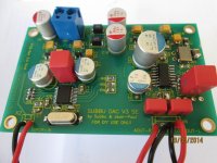
Finished my build (two of them), sounds very good. First thing that hit me was separation of instruments. Should listen more once it breaks in. Anyway, will be adding JG buffer to it. Thanks JP, Subbu for your efforts and also bcmbob for the starting this build thread. It helped me in completing this project at first go.
P.S: I have not yet cleaned the boards after the build, will do it soon.
P.S: I have not yet cleaned the boards after the build, will do it soon.
Attachments
Last edited:
Hi, good to see that it works and that you are happy with the results. Your soldering could be somewhat better, I think you are lucky that the XO works. Why did you use too large electrolytic caps ? I mean their size....results in too long wiring. Trust me, you will have better results with smaller SEPC caps soldered with short lead wires. Since max. voltage is 5 V you can use 6 or 10 V versions.
Also one of the output filter caps could be reversed. Think of them as electrolytic caps and now see where their - is connected.
Also one of the output filter caps could be reversed. Think of them as electrolytic caps and now see where their - is connected.
Last edited:
So I've finally completely finished it all.
I find case work a real pain, I'm usually unsatisfied with how my diy gear ends up looking.
I used a hammond 1455 series case with my own front plate. I won't go this way again, as the bottom plate is loose enough to rattle unless you tap the screw holes for larger screws. (PITA).
As you can see from the pics, I was paranoid about picking up hum from the mains leads down the side of the case, so I rigged up a steel cover for them.
I think it turned out pretty neat. The only bit that bugs me is trying to drill a straight row of ventilation holes. It's probably overkill anyway, but the pass transistor gets reasonably warm, and I like things cool.
Now that I've had a more serious listen, I can say I'm delighted with the sound. It's certainly a step up from the built in decoders in my receiver. 🙂
Parts are all standard GB bom.
Haven't had a chance to take it down to my friend in the hifi shop yet.
Thanks for a great project everyone.
Cheers,
Mark
A few pics:
Very nice job ! Did you measure the DC voltage at the first filter cap ? Just curious as those transformers give way more voltage than expected (usually).
I see you RF decoupled the inputs to the case ?
JP,
Thank you for your feedback. I dint realize that the cap will make that much difference. I will make the change. Will also flip the output filter caps. The XO on this board did not see much heating. On other board it did but it still is working. So I am little lucky with these guys.
Now, I see that the voltages on pin 9 and 10 (Cp and Cn) of ES9023 are not same. Cp is 1.57V and Cn is -1.87V. Can you tell me why that would be the case? I think it should be same but not sure why they are not. DAC itself is working and I can hear music but am not sure if this will impact the sound in any way. The voltages Atupi measured Cp=1.743V and Cn=-1.73V. So I have done something wrong? It is the same on both the boards.
Thanks
Those are the pins for the charge pump cap. Please try to understand that function. I would not bother to measure the Cp and Cn pins as the internal structure of the chip is unknown to us. Since it is a charge pump high frequencies are found there so a standard DMM is not enough.
The negative voltage at the Vneg pin is more relevant IMO.
The negative voltage at the Vneg pin is more relevant IMO.
JP,
Can you check the voltages on these pins in your DAC? I know I am troubling you but want to be sure that it does not impact the sound quality.
Thanks
Can you check the voltages on these pins in your DAC? I know I am troubling you but want to be sure that it does not impact the sound quality.
Thanks
Those are the pins for the charge pump cap. Please try to understand that function. I would not bother to measure the Cp and Cn pins as the internal structure of the chip is unknown to us. Since it is a charge pump high frequencies are found there so a standard DMM is not enough.
The negative voltage at the Vneg pin is more relevant IMO.
Will also flip the output filter caps.
You only need to flip one of the output caps (if you believe in polarity of non polar parts that is 😉 ) !
Very nice job ! Did you measure the DC voltage at the first filter cap ? Just curious as those transformers give way more voltage than expected (usually).
I see you RF decoupled the inputs to the case ?
Yeah, de-coupled with 56R and 10nF. Any issues with doing that?
So I did as you suggested and checked the DC voltage on the first cap...

I'm getting a little over 20V from a transformer that is 9VAC on the secondary. So about 7-8 V too much!
🤐
No wonder the poor pass transistor is getting warm. Dammit!
I ran it for about 4 hours today and measured at various times with a thermocouple. Looks like settles around 33 deg above ambient (that includes the air inside the case warming up as well). On the hottest day I would be listening to music the transistor case will be ~70deg. This is still well within the safe operating area for the ~1.2W dissipation, but I'm not exactly thrilled.
So now I have three options:
1. Just don't worry about it. It works and should not blow up.
2. Reposition the transistor to under the power supply PCB, and use the 160x160mm aluminium base as a heatsink. Should be plenty to keep it a bit cooler.
3. Order a new transformer. This is the best fix as far as heat and power goes, but also the most expensive and annoying.
None of these appeals to me. What would you guys do?
Cheers,
Mark
Order the transformer from the BOM. Silent, right voltage, tested etc etc. Really a 10 $ dilemma. I am thinking of omitting the BOM for the next project 😀
70 degrees is too hot, safe operating area or not. This is a 55 tot 80 mA using DAC. Why waste energy in heat ? If the right transformer is used no heatsink is required and you can use the DAC in a closed case (no ventilation). It is IMO good design to calculate and choose a transformer to the necessary output voltage. Wasted energy simply results in useless heat. The art is to loose as little energy as possible while staying within a normal operating area.
70 degrees is too hot, safe operating area or not. This is a 55 tot 80 mA using DAC. Why waste energy in heat ? If the right transformer is used no heatsink is required and you can use the DAC in a closed case (no ventilation). It is IMO good design to calculate and choose a transformer to the necessary output voltage. Wasted energy simply results in useless heat. The art is to loose as little energy as possible while staying within a normal operating area.
Last edited:
Yeah, I don't think it's a $10 transformer in Australia. The only place I could find it easily was (I think) Mouser. The shipping from O/S pumped up the price.
In theory, this one which was available locally should have been fine. I didn't expect a variation of around 60% from spec. Live and learn I guess....
I'll look at the options again. You're right, wasting heat and power is silly. I don't think I'll be satisfied unless I have it working properly, not just a band-aid fix.
Thanks JP.
Edit: Just had a look at the mouser "australia" site. $6.95 for the transformer. $39.00 for the shipping. Umm, no.
Guess I'll be trawling through some local places again. 😀
Mark
Last edited:
Small parts can be bought here in the States and mailed via regular post at quite a savings. I've sent lots to Europe and other countries - not sure about Australia. PM me your address data and we can investigate the potential cost.
Thanks Bob, that's a really generous offer, and I may end up taking you up on it.
For now, I think I'll try a lower voltage version of what I had. In every other respect it was fine; it ran cold & silent, easily and cheaply available and it fit perfectly. With my new found knowledge, I'll just get a lower rating on the secondary.
I'll PM you if it doesn't work out 🙂
Cheers,
Mark
For now, I think I'll try a lower voltage version of what I had. In every other respect it was fine; it ran cold & silent, easily and cheaply available and it fit perfectly. With my new found knowledge, I'll just get a lower rating on the secondary.
I'll PM you if it doesn't work out 🙂
Cheers,
Mark
- Home
- Source & Line
- Digital Line Level
- Build thread - building the Subbu DAC V3 SE