Thanks Bob. Can anyone of you electronic wizard scan a couple of pics for me and possibly catch any obvious mistake if there is any? That would be a great help. First smd solder project, learned a lot... Patience most of all 🙂
Step 1 - load the pictures properly. I've reloaded them for you in this post.
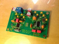
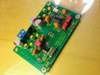
Step 2 - take a look at U5. Some of the pins look like they might be shorted.
Step 3 - hook up the +5v power supply and see if the regulators are providing the correct voltages.
Step 4 - hook up a source and see if sound comes out.
----Gary
Attachments
Last edited:
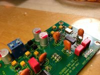
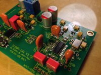
I'm not the expert, but I believe the first step is to attach the power supply and test for proper voltages at L3, 4, 5 and 6. Have you done that? (second picture - first post)
C35 C22 polarity
Check the polarity of the SAL RPM capacitor C22 the black line indicates - not +.
With regards
Martin
I'm not the expert, but I believe the first step is to attach the power supply and test for proper voltages at L3, 4, 5 and 6. Have you done that? (second picture - first post)
Check the polarity of the SAL RPM capacitor C22 the black line indicates - not +.
With regards
Martin
Last edited:
Thanks Bob. Can anyone of you electronic wizard scan a couple of pics for me and possibly catch any obvious mistake if there is any? That would be a great help. First smd solder project, learned a lot... Patience most of all 🙂
Is there a way to check if it's working properly without a source?
C31 on the underside of the board is unpopulated.
Thanks a lot for the help
An externally hosted image should be here but it was not working when we last tested it.
An externally hosted image should be here but it was not working when we last tested it.
An externally hosted image should be here but it was not working when we last tested it.
An externally hosted image should be here but it was not working when we last tested it.
An externally hosted image should be here but it was not working when we last tested it.
An externally hosted image should be here but it was not working when we last tested it.
Hi Seemtorecall,
Please double check datasheets on the Sal-rpm caps (c22 & c35). I believe the band marks negative side. I too bought the korben gb parts and c31 was missing. However I'm getting good results with just c34 populated. Cheers.
Thanks everyone I really appreciate all this help. Yes forgot to mention C36 sprung out of my tweezers and was gone forever, have to order a new one... damn. I'll go through all these comment and check the board, thanks again!
Tim
Tim
Hi Seemtorecall,
Please double check datasheets on the Sal-rpm caps (c22 & c35). I believe the band marks negative side. I too bought the korben gb parts and c31 was missing. However I'm getting good results with just c34 populated. Cheers.
Okay that is good to know, I have to order C36 anyway so I think I'll try ordering C31 too and possibly see what difference it makes.
I'll second all the remarks above... once you think it is complete just hook it up to the power supply and measure the voltages.
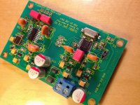
You can work your way down from the regulators down to the IC's... I had a bit of trouble around the WM8804 until I carefully reflowed a couple pins.
Once you have verified that all voltages are within ballpark you can connect it to play some music.
Btw. To my eyes that's a fine soldering job!
You can work your way down from the regulators down to the IC's... I had a bit of trouble around the WM8804 until I carefully reflowed a couple pins.
Once you have verified that all voltages are within ballpark you can connect it to play some music.
Btw. To my eyes that's a fine soldering job!
I'll second all the remarks above... once you think it is complete just hook it up to the power supply and measure the voltages.
You can work your way down from the regulators down to the IC's... I had a bit of trouble around the WM8804 until I carefully reflowed a couple pins.
Once you have verified that all voltages are within ballpark you can connect it to play some music.
Btw. To my eyes that's a fine soldering job!
Thanks Stixx!, I think it wen't okay for a first smd experience, I'll follow that procedure and check the voltages when the last issues are corrected.
Let me just add again that opening the package for small SMD parts directly over the PCB helps eliminate much of the tweezers hazard. If you have to flip it put a small amount of liquid/paste flux on the tweezer tips and use minimal pressure keeping everything down on the board.
I use a dental pic to orient and slide the piece into position. As suggested earlier, the target pads should be fluxed prior to placing the part.
I use a dental pic to orient and slide the piece into position. As suggested earlier, the target pads should be fluxed prior to placing the part.
Let me just add again that opening the package for small SMD parts directly over the PCB helps eliminate much of the tweezers hazard. If you have to flip it put a small amount of liquid/paste flux on the tweezer tips and use minimal pressure keeping everything down on the board.
I use a dental pic to orient and slide the piece into position. As suggested earlier, the target pads should be fluxed prior to placing the part.
Thanks for the tip bob, yeah I changed tactics after my tweezers shot that capacitor into the unknown, learning by doing I guess :/
Let me just add again that opening the package for small SMD parts directly over the PCB helps eliminate much of the tweezers hazard. If you have to flip it put a small amount of liquid/paste flux on the tweezer tips and use minimal pressure keeping everything down on the board.
I use a dental pic to orient and slide the piece into position. As suggested earlier, the target pads should be fluxed prior to placing the part.
I open my small parts into a small plastic bowl and then pick them out with good quality tweezers designed for SMD work - never lost a part yet.
Anti-Magnetic Precision Tweezers - Jaycar Electronics
The operative word being "yet"  😀
😀
I read somewhere lately that placing the PCB inside a shallow cardboard box helps to restrict the flight path.😉
😀I read somewhere lately that placing the PCB inside a shallow cardboard box helps to restrict the flight path.😉
Last edited:
I got the spdif toslink module from twisted pear audio, and it has the option to be configured for "3.3v TTL output voltage" or "Consumer level output", which one should I go with?
The operative word being "yet"
I read somewhere lately that placing the PCB inside a shallow cardboard box helps to restrict the flight path.😉
lol - perhaps one day I may agree with your fear of flying SMD parts, but until that day comes, I'm just sharing my thus far effective experience.
I think it depends a lot on the quality of the tweezers. The ones I linked to work work very well - they line up perfectly and don't try to cross over at all. I have other sets that I am certain would eject an SMD part as quickly as I could pick up a tiny part.
or perhaps it's just the operator 😛
I got the spdif toslink module from twisted pear audio, and it has the option to be configured for "3.3v TTL output voltage" or "Consumer level output", which one should I go with?
Can anyone help with this question? Last thing before it's ready to fire up. Thanks!
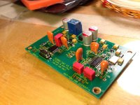
I need to order a new ceramic cap for C17, which has stopped progress. The build has been fun so far despite Q2 being a bit challenging.
An externally hosted image should be here but it was not working when we last tested it.
Last edited:
- Home
- Source & Line
- Digital Line Level
- Build thread - building the Subbu DAC V3 SE