Bnorrish, I tried to order that kit but they were out of stock at at that time, but their step by steps helped me immensely.
As for the complexity of this kit for a novice...it is not in the parts but really just the SMD size. The only challenge is not knowing if a signal is flowing into 8804 and then from 8804 to 9023. I have enjoyed putting this together even though mine does not work 🙂
Are there any more pcb not accounted for? I would like to get another if possible.
Jean-Paul can you confirm C31 or C34 ? Fred showed me a BOM that is different to mine where it mentions that either C31 or C34 should be populated.
Last edited:
Hello,
After a lot of conversation trought PM with Subbu, who sad that he can sell me one PCB, still no answer for 3 weeks.
I see that some members have problems with Subbu dac.
Perhaps anybody can sell me one destroyed PCB and I will try to fix it?
I really want to try that DAC, but I don*t now the way to buy it, because I was too late at GB.
Thank you,
Davorin
Hi,
It's my first time smd soldering and have no problem but the Fox XO because of the short pcb here.
I use a lot of flux here and suceed to solder but as Xo crystal are known to be fragile, how can I check it to be sure it's not burned ?
Can listen to it because waiting for R2 : 10 k smd resitor from Mouser (for 2 weeks... waiting is not a problem because JP & subbu learn me the WoW : Wisdom of Waiting)... just asking myself if I need to buy a Xo spare ?
Last edited:
R2 is 75R, are you refering to 4x10k resistor array ?
Normally if your Xo is working you should measure 3.2-33V on pin 11 of ES9023.
Normally if your Xo is working you should measure 3.2-33V on pin 11 of ES9023.
The Blues of the Fox
Sorry my mistake : i talk about R1 on the DAC PCB (near rn1 and C1).
I suceed soldering the XO at 350° iron pen temperature, but as I try many times and the XO was very hot... i asking myself how to check and the need to add a line to my Mouser's waiting list !
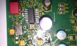
for others : As you see on the first picture you must put the iron pen between (below is the right word) pcb & XO crystal... which is not easy ! Flux helps.
Sorry my mistake : i talk about R1 on the DAC PCB (near rn1 and C1).
I suceed soldering the XO at 350° iron pen temperature, but as I try many times and the XO was very hot... i asking myself how to check and the need to add a line to my Mouser's waiting list !
for others : As you see on the first picture you must put the iron pen between (below is the right word) pcb & XO crystal... which is not easy ! Flux helps.
Attachments
Last edited:
And you don't have a 10k resistor, even leaded non-smd in your drawer just for test ? Value is not so critical in that position.
I told you how to test your XO, even without that 10k resistor soldered.
For smd i set 280-290 degrees and always leaded soldering alloy, i hate non leaded solder.
I told you how to test your XO, even without that 10k resistor soldered.
For smd i set 280-290 degrees and always leaded soldering alloy, i hate non leaded solder.
Last edited:
I miss it, have to re read... yes I maybe have a big bulk one 10 k...
Is there a tip for a cheap flux liquid cleaner ?
Is there a tip for a cheap flux liquid cleaner ?
Last edited:
 .
.Here is a link to a Google doc that may help debugging. The standard/acceptable values still need to be added, but got my fingers crossed that those in the know will fill in the information. Pleas report any errors/omissions discovered. Plan to upload a matching graphic soon.
Caution: Work in progress!!
JP/Subbu DAC test points.
Caution: Work in progress!!
JP/Subbu DAC test points.
Last edited:
I used Abracon in v2.6 which was my first smd build. I cooked it quite well, but it survived. One member soldered it wrongly, and it still worked after the orientation was corrected. So, it seems to be quite rugged. I wonder the Fox XO is more fragile and requires handle with more care.....
First time round I had Q2 soldered in correct orientation but with 4 x magnifier I found one pad still not connected so I removed it and placed it on its side only to realize I had wrong orientation - that meant pin2/ground was getting Vdd and explained why my voltages around it were off. Put it back correctly and voltages are good. As for the integrity of Q2, still not sure. But I plan to replace Q1, test and then replace Q2 if all else fails.
From what I can tell my 8804 and 9023 are getting the correct voltages. Hoping Atupi will provide a list of his voltages since his works 🙂
So far a really enjoyable project hey and worst case if it still does not work, I have learnt a lot from schematics, smd soldering and I will have a working 5V power supply for future projects or my SB Touch 🙂 So thx Jean-Paul, Korben and Subbu.
The Google points doc has been updated in an attempt to include all pads. Some will not be necessary but are included none the less.
Position: t = top - b = bottom / l = left - r = right as shown on PCB.
U 1-6 pin-out images were added for reference.
Probe path starts at top left to bottom - bottom to top in columns.
The sheet can be printed or downloaded as a spreadsheet from the "File" menu drop-down.
JP/Subbu DAC Read Sheet
Position: t = top - b = bottom / l = left - r = right as shown on PCB.
U 1-6 pin-out images were added for reference.
Probe path starts at top left to bottom - bottom to top in columns.
The sheet can be printed or downloaded as a spreadsheet from the "File" menu drop-down.
JP/Subbu DAC Read Sheet
Last edited:
Sorry but i can't edit in that google doc.
Here is the voltages measured WITHOUT signal on input:
Wm8804:
Pin - Measured
1:3.29 11:0.814
2:3,29 12:0.036
3:0 13:0.83
4:0.039 14:1.685
5:3.28 15:1.665
6:3.29 16:1.684
7:3.29 17: 0.032
8:0 18: 0
9:0 19: 3.3
10:0.52 20: 1.641
ES9023:
1: 1.685 9: 1.743
2: 1.665 10: -1.730
3: 0.038 11: -3.389
4: 0 12: 0
5: 3.604 13: 1.65
6: 1.150 14: 0
7: 0 15: 3.57
8: 0 16: 3.60
Attachments
Last edited:
Sorry but i can't edit in that google doc.
Here is the voltages measured WITHOUT signal on input:
It would be good to add the correct polarity to your measurements. A few of the ES9023 pins have negative voltage.
---Gary
Tips to check LDO voltage
Tips :
As it is very difficult to look at shorcuts between the three pads of the LDO regs, use the voltmeter box in buzz mode to find continuous voltage. The pad on the midle with the black pen and red pen with left and after right : no sound from the voltmeter is correct : if buzzzz then you have a little shorcut.
As Atupi wrote : With 5V INPUT AT X1 and without L5 & L6 you must have 3,3v (3V3) after the LDO regs at C15+ & C27+ : if correct you can put L5 & L6.
For U3 and U4 LDO regs : use the buzz function to detect shortcuts if DAC Chip is already on the pcb.
If L4 not already on PCB you can check too the voltage before it at C26+ : 3,6 V (3V6).
Two cents for beginners like me, but hope it helps : i had a shortcuts on U5 ldo i have not seen with x4 glasses : no led light on the PSP pcb when switch on : it was safe with the Atupi's tip : don't put the L coil before checking the LDO voltage to avoid burning the chips.
Last edited:
Sorry but i can't edit in that google doc.
Here is the voltages measured WITHOUT signal on input:
Wm8804:
Pin - Measured
1:3.29 11:0.814
2:3,29 12:0.036
3:0 13:0.83
4:0.039 14:1.685
5:3.28 15:1.665
6:3.29 16:1.684
7:3.29 17: 0.032
8:0 18: 0
9:0 19: 3.3
10:0.52 20: 1.641
ES9023:
1: 1.685 9: 1.743
2: 1.665 10: -1.730
3: 0.038 11: -3.389
4: 0 12: 0
5: 3.604 13: 1.65
6: 1.150 14: 0
7: 0 15: 3.57
8: 0 16: 3.60
Thx Atupi...appreciated 🙂
My 9023 is spot on with yours but my 8804 are off :
9 is 1.18v vs 0
14 is 1.18 vs 1.6
16 is 1.09 vs 1.6
so does this mean Q1 is def. shot? pins 14 & 16 also go to 9023 so maybe thats why i have issues? Gary also commented about the 1.6v I should be seeing....
Last edited:
Sorry Adrian, If you PM me a usable email address I'll set you up as a collaborator. I will input what you have provided today but let me know if there are problems in the future. It would be great to have JP, Subbu, Gary B and a few others as collaborators. If interested, send email info.
- Home
- Source & Line
- Digital Line Level
- Build thread - building the Subbu DAC V3 SE