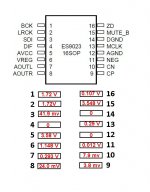
Here are my voltages for WM8804:
1 - 3.27V
2 - 3.25V
3 - 0
4 - 0.04V
5 - 3.25V
6 - 3.26V
7 - 3.26V
8 - 0
9 - 1.18V
10 - 0.52V
11 - 0.68V
12 - 0.03V
13 - 0.01V
14 - 1.18V
15 - 1.64V
16 - 1.09V
17 - 0.03V
18 - 0
19 - 3.27V
20 - 1.61V
1 - 3.27V
2 - 3.25V
3 - 0
4 - 0.04V
5 - 3.25V
6 - 3.26V
7 - 3.26V
8 - 0
9 - 1.18V
10 - 0.52V
11 - 0.68V
12 - 0.03V
13 - 0.01V
14 - 1.18V
15 - 1.64V
16 - 1.09V
17 - 0.03V
18 - 0
19 - 3.27V
20 - 1.61V
All the voltages that are around 1.18v should be closer to 1.65v. When you read 1.65v it really means there is an AC signal going back and forth from Vdd (3.3v) to ground and the average is 1/2 of 3.3v or about 1.65v. When it reads low then it looks like the oscillator isn't working. I'd check Q1 and see if it's got a problem.Here are my voltages for WM8804:
---Gary
I long suspected Q1 but dont know how to test it apart from checking volt.
I read somewhere how easily it can be broken if dropped or overheated.
I read somewhere how easily it can be broken if dropped or overheated.
Try to desolder c34. Around q2 you can only check the 3.3 v that feeds the clock.
Do you have C31 and C34 populated?
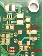
Try to desolder c34. Around q2 you can only check the 3.3 v that feeds the clock.
Is that to Neville, me or both?
Neville 🙂
I've built 3 kits, two of them worked from first and one had 50mhz clock distroyed from excessive temperature.
How did i troubleshooted? I used a good one and in first test i fed the Es9023 from defective kit with I2S signal (R4,R5,R6) from working kit>result no sound. Conclusion: problem was in the second part meaning ES9023. You can do the same if you know someone with a working kit nearby, so you can decide the problem is in the first stage (spdif receiver) or the second stage (dac).
Sorry for my english 🙂
An externally hosted image should be here but it was not working when we last tested it.
Last edited:
You mean one kit ?
If yes, one was for me and two for somefriends who like diy but they dont like smd soldering.
If yes, one was for me and two for somefriends who like diy but they dont like smd soldering.
Atupi I noticed you have C34 populated, why are you suggesting I remove C34? One of my ESS9023 pin out values wrong?
I have C34 but in a different position if i see well, i said to remove it just for testing purposes
Atupi, We did a simul-post. That is the first working standard build I have seen posted. I was just saying we need to get one operating and posted, but you beat that by 3.
Since I only have one board - what do you consider the split point between stages? I have a mini2496 and a DAC5 that could possibly used for the test you mentioned, but need to know where to splice in.
Since I only have one board - what do you consider the split point between stages? I have a mini2496 and a DAC5 that could possibly used for the test you mentioned, but need to know where to splice in.
R4, R5, R6 is the splitting line, BUT if i read well you have a small voltage on Es9023 pin 11, you should have 3.2-3.3V.
If your voltage is zero point something i'm almost 99% sure your 50mhzclock is not doing his job.
http://www.diyaudio.com/forums/digi...-building-subbu-dac-v3-se-12.html#post3710843
If your voltage is zero point something i'm almost 99% sure your 50mhzclock is not doing his job.
http://www.diyaudio.com/forums/digi...-building-subbu-dac-v3-se-12.html#post3710843
Hey Atupi can you give us the pinouts for 8804 and 9023? That way we have a record of a working one 🙂
Bob and I could go on all week until cows come home and even then .......
Bob and I could go on all week until cows come home and even then .......
Quick and messy schematic for better understanding of this simple DAC:
Neville, you mean:
http://www.wolfsonmicro.com/documents/uploads/data_sheets/en/WM8804.pdf
WM8804 datasheet, Pinout ,application circuits 1:1 Digital Interface Transceiver With PLL
An externally hosted image should be here but it was not working when we last tested it.
Neville, you mean:
http://www.wolfsonmicro.com/documents/uploads/data_sheets/en/WM8804.pdf
WM8804 datasheet, Pinout ,application circuits 1:1 Digital Interface Transceiver With PLL
An externally hosted image should be here but it was not working when we last tested it.
- Home
- Source & Line
- Digital Line Level
- Build thread - building the Subbu DAC V3 SE