where are all the builders
Just curious to see if anyone has gotten around to building their DAC yet? I know quite a few people are waiting for group buy parts which must be frustrating. But others must have gotten boards directly and then ordered their parts on their own. We've heard from a few but it's been rather quiet.
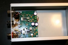
Since it was unusually cold in California, I spent today indoors soldering up a V3 board. I'm mostly done but waiting for the 50Mhz crystal oscillator to arrive. Here's a picture of the progress so far. And I promise Jean-Paul that I will clean up the solder flux before I'm done.
---Gary
Just curious to see if anyone has gotten around to building their DAC yet? I know quite a few people are waiting for group buy parts which must be frustrating. But others must have gotten boards directly and then ordered their parts on their own. We've heard from a few but it's been rather quiet.
Since it was unusually cold in California, I spent today indoors soldering up a V3 board. I'm mostly done but waiting for the 50Mhz crystal oscillator to arrive. Here's a picture of the progress so far. And I promise Jean-Paul that I will clean up the solder flux before I'm done.
---Gary
Attachments

Looking good. I am starting up my build. Needed to buy some 2.0 reading glasses for the small parts. 🙂
DAC V3
Is up and running for about one week. I did not use any exotic components - I've used 4.7 uF MKS for positive and negative rail decoupling at the ES chip. Replacement of the 1uF mlcc charge pump capacitor by and mkp (the blue one on the picture) did not affect the sound either. Sound is open, clean and detailed - but who am I to judge - just build and listen...
Thank you guys! 😉
Attachments
Paul, Could you give a little more detail please. Is the charge pump cap connected to A & B only. Can't tell if that is a bypass type setup from the photo.
C32 & C35 are bare?
C31 installed on bottom?
Thanks.
 [/url][/IMG]
C32 & C35 are bare?
C31 installed on bottom?
Thanks.
Hi Bob,
C28 is the blue cap located at the position of your picture - 1uF epcos
I've used 100nF mlcc at C34 and C36 near the DAC chip. C22 is a 4.7 uF mks (gray) and (C31-C32-C35) is also a 4.7uF gray (bottom side at the C31 pads - otherwise I couldn't mount C28 on the top side). Hope this helps - I'm not a fan of using large caps after a regulator - but feel free to do otherwise. Input caps before the mics are Sanyo Oscons 100uF. C29 and C30 are old stock Philips film caps.
Paul
Ok, I think I understand (C31, 32, 35 on bottom). I'm very happy that your V3 build is working, but my bigger concern is centered on what might be called a "standard" build. Did you establish operation with something like the BOM shown in post #113 first and then tweak/upgrade. I think there will be many of us seeking a less sophisticated base. JP has often and correctly reminded us this is not a project for beginners. However, it would be comforting to know operation is achievable and stable using at least one universal collection of parts.
Last edited:
Bob,
For c28 use as recommended. The BOM mentions for the (C31-C32-C35) various options - the pcb layout allows you to "mount" various types. I've chosen one MKT 4.7uFand a mlcc ceramic 100nF for each rail. The pcb-s are of great quality - I've already swapped various components without have problems with the pcb. You can always replace components at a later stage to find out what you do prefer.
For c28 use as recommended. The BOM mentions for the (C31-C32-C35) various options - the pcb layout allows you to "mount" various types. I've chosen one MKT 4.7uFand a mlcc ceramic 100nF for each rail. The pcb-s are of great quality - I've already swapped various components without have problems with the pcb. You can always replace components at a later stage to find out what you do prefer.
Asgaard, when reading your name I remember a promise I did not keep(which is a big no no in my book normally). Just printed out your address. I assume you can still use the promised parts ?
BTW is that a self wound SPDIF transformer ?
😉
BTW I like the looks of the board. Too bad I can't get hold of those caps here. You will have a hard time soldering the XO with the 4.7 µF in place !
BTW is that a self wound SPDIF transformer ?
And I promise Jean-Paul that I will clean up the solder flux before I'm done.
---Gary
😉
BTW I like the looks of the board. Too bad I can't get hold of those caps here. You will have a hard time soldering the XO with the 4.7 µF in place !
Last edited:
Sounds good. I'm on the parts GB, but I jumped ahead and did my own sourcing for an early start. Messed something up, so will wait for the GB package for another shot at the basic build.
I am working on the PSU. Everything is soldered onto the board. I believe I have a bad transformer which seems surprising. Takmura 3FD-316. I am only measuring only 0.2 v AC on pins 5, 6, 7, 8. Pins 1 & 2 measure 122 V AC, pins 3 & 4 measure O V. What do you think?
tamura 230 V
Just a 2 cents for beginners like me :
For the 230 V : don't forgett a jumper between Tamuras' Pins 2 & 3. Easier to do before soldering the big tamura.
Again for curiosity : what is the need of the 0,1 uF just after diodes rectifier ?
I have a 4.97 V. But I use a red led I already have. Is the green genuine led important here (2.1 V & 20 mA) ?
just wait a small resistor from Mouser to listen to the SUBBU V3
The 100 nF cap is to improve the HF behavior of the electrolytic cap but to be honest I think the Pana FC do a good job already. We intended to have RF/HF filtered before it can enter the regulator.
You can use a red LED (normally used for error condition) but maybe you feel better when you test it first with for instance 1k8 on a 5 V supply to check if it is not too bright. I suffer from "bright LED" allergy especially when blue LEDs are concerned so it could be something personal.
You can use a red LED (normally used for error condition) but maybe you feel better when you test it first with for instance 1k8 on a 5 V supply to check if it is not too bright. I suffer from "bright LED" allergy especially when blue LEDs are concerned so it could be something personal.
Thank you Jean-Paul,
I just use it because forgett it in my BOM with Mouser ! This led come from a broken cd player (front plate : swicht on.off power supply led !) : It's very bright, i think it will break. my question was about the use of this led : just to signal the on/off of the PS PCB or used for regulating ?
About the 100 nF : and there is too the SMD 1 uf film cap...maybe lower esr than the FC cap and 1 uf is faster than the 2000 uF cap.
I will try because often with the caps they add a little sound signature which can help for final set up as each global hifi system is different like the taste of the owner.
For the diodes rectifier i use a classic slow one. I never had sucees with ultra fast diodes in CD player, ok they are to avoid noise but i never find gooder result that slow ones!!!!! Better is the work about blending the caps with my own experiences. But it's a detail.
If the LED is too bright just measure the voltage over the series resistor for the LED. Then calculate the current. Normal 3 mm red LEDs give enough light at 2.5 mA current. High efficiency/low current types give too much light at 2.5 mA.
The LED is just for power on indication and to be a small load when there is no DAC connected. The LED is the only extra feature of our DAC (except for producing good sound) 😉
BTW just try a LT3080 without the power LED as load and it will put out the full input voltage....So I always use a power on LED with all LDO regs and certainly with negative regulators as they don't work as intended with no load.
Last edited:
Question.
Is there anybody who has finished dac could put as many tips and tricks in one place for beginning to build to have a reference ?
Is there anybody who has finished dac could put as many tips and tricks in one place for beginning to build to have a reference ?
Hi VoL,
The two thread are enough imho. It was my first smd soldering and with rhe YT links and flux it is ok at the first try.
Take care with the Ldo, then the polarized smd caps( 4,7 uF)
Check voltage before soldering smd self coil as Atupi wrote.
For the wm88005 chip, check with a X4 glasses.
Salt, pepper...then eat.
- Home
- Source & Line
- Digital Line Level
- Build thread - building the Subbu DAC V3 SE