Fantastic Tvicol! Guess you not use a mobilephone for your great shots?
Thanks ! In fact I use one https://jolla.com/jolla/
Regards,
Tibi
Tibi, do You fel this dac can do better with a tube buffer ? How do You like it as it is without buffer ?
Hi,
I would like to know if I can use this kind of transformer for the PSU:
VB2.3/2/9 - BLOCK - TRANSFORMATEUR 2.3VA 2X 9V | Farnell France
Thanks
I would like to know if I can use this kind of transformer for the PSU:
VB2.3/2/9 - BLOCK - TRANSFORMATEUR 2.3VA 2X 9V | Farnell France
Thanks
Sometimes the resulting DC voltage before the regulator is too high with a 9V type... depending on regulation of the transformer. This will make the BD140 run unneccessarily hot.I would like to know if I can use this kind of transformer for the PSU:
You should get away with a lower voltage one, like this one --> VC 3.2/2/8 - BLOCK - TRANSFORMER, 3.2VA, 2 X 8V | Farnell France
SORRY: didn't check the footprint of the transformer!
Hey guys,
finally finished my assembly of the subbu dac, sounds great but I have one problem. It doesn't seem to play 192 khz files... i do get a "sound" but it doesn't seem to be decoded properly. Anyone of you had the same problems? I use Jriver as a source. Tried foobar as well but same problem :-/ Would be grateful for any ideas...
finally finished my assembly of the subbu dac, sounds great but I have one problem. It doesn't seem to play 192 khz files... i do get a "sound" but it doesn't seem to be decoded properly. Anyone of you had the same problems? I use Jriver as a source. Tried foobar as well but same problem :-/ Would be grateful for any ideas...
Hey guys,
finally finished my assembly of the subbu dac, sounds great but I have one problem. It doesn't seem to play 192 khz files... i do get a "sound" but it doesn't seem to be decoded properly. Anyone of you had the same problems? I use Jriver as a source. Tried foobar as well but same problem :-/ Would be grateful for any ideas...
Hi
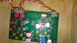
Post a close pic of WM8804 chip.
Might be a bad solder there... or on the SPDIF line 😉
Regards,
Phil
Pas mieux !
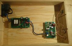
Maybe I would put the spidf cable less closer than the 2 output ones by positioning the first one (spidf) near the wood plan and let the other 2 floating in the air like they are now ! On the photograph they seem to close!
just two cents, I believe Korben69 has the right input. In another way, you could have a shorter cable by putting this spidf at the opposite side in front of the output pcb pins. You just have an other hole on the cabinet near the actual spidf : put here the two RCAs instead and use one of the old RCA holes for the spidf !
but this a detail. Surely a cold joint somewhere.
Last edited:
hey guys ... thanks for all your replys!!! first off, phil, you did the soldering on the board and tested it, so it should be fine ;-) will post a pic of wm anyway.
my bnc cable might be faulty, its a bit old ... will try to test with a new one in the next days
to clarify: 44 khz and 48khz works fine, everything more gives wierd electronic noises like when you send dts encoded sound to a device that cant decode dts - hope you can understand what i mean ;-)
I think it might be a software problem ... don't have any other source to verify this theory though ... the chain is: Spdif out from my soundcard using wasapi by jriver audio player to the dac directly into my amp
eldam: sorry i didn't really understand - so you would put the spdif cable even further away? or switch position with the rca-outs? what is too close together? my girlfriend knows a little bit of french, so you could try to say it in french then i might understand better *g* ;-)
P.S. hope this picture quality is better - my mobile cam is **** ;-) will try to get a real camera if these pics are not good enough
Attachments
Hello,
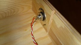
one look at your twisted cables literally makes me shiver 😉 I would use at least a shielded wire for microphones 😉
Shielded cable - Wikipedia, the free encyclopedia
Best regards,
one look at your twisted cables literally makes me shiver 😉 I would use at least a shielded wire for microphones 😉
Shielded cable - Wikipedia, the free encyclopedia
Best regards,
WM8804 solders look fine.
I've tested boards and give them some burn-in time.
So, this section should be Ok.
Check your SPDIF connexions.
Try to shorten wires lenght.
Post closer pics of them 🙂
I suggest you to place connectors in front of PCB pins output.
Regards,
Phil
I've tested boards and give them some burn-in time.
So, this section should be Ok.
Check your SPDIF connexions.
Try to shorten wires lenght.
Post closer pics of them 🙂
I suggest you to place connectors in front of PCB pins output.
Regards,
Phil
Last edited:
Soldering quality is in fact nice... well done Phil. 😉
I also can't spot any mistakes in your wiring... I think Eldam meant to separate the S/pdif line from the output lines a bit. But I doubt that would cause your problems... only make the S/pdif wire as short as possible.
Dumb question: does your soundcard support higher than 48kHz files..? that's where I would investigate.
Last edited:
- Home
- Source & Line
- Digital Line Level
- Build thread - building the Subbu DAC V3 SE