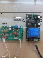
Why not to try to put the transformer farer : here it's very near the Wolfson !
Try to put the PS pcb // to the DAC PCB :transformer in the high right corner, the power wire the farer you can of the spidf plug (here put it on the right side of the box !
If you can go for a larger box with 1O cm of wire between the 2 pcbs...
If you can : go for true 75 ohms BNC plugs : both on the Subbu and your source (or stay like that if you can change the plug on your source).
(personal advisse : I found the 2 x O.1 uf green vishays on your PS gave an horrible result with me : I switched for the Wimas of the BOM)
JP is this layout ok?I'll make the box out of aluminum.
It is OK if you mean with "wall" that you will use a metal screen at that spot. I do think you will have a problem making a safe conection of the 230 V AC wiring to the 230 V mains connector.
You case is a tad too small I guess. A slightly larger case will give the possibility to turn the PSU 90 degrees ( and to the upper right corner of the case) which creates more distance between the transformer and the DAC board.
Last edited:
I have no words for this except that you maybe can mill a second case for me 🙂 .... Beautiful ! I have thought about such cases long ago but left the idea as I could not get it done for acceptable costs.
Still be aware that you will need some space for the radius of the wiring. Better have wiring "floating in the air" than it touching the case (even if it is the insulation that touches the case). Mmm, that were many words...
Still be aware that you will need some space for the radius of the wiring. Better have wiring "floating in the air" than it touching the case (even if it is the insulation that touches the case). Mmm, that were many words...
Last edited:
What color would you prefer?
Seriously,we need to wait to see how the prototype turns out first.
Seriously,we need to wait to see how the prototype turns out first.
Normally I would say black but plain aluminium with a slight profile in it like the Mac Mini case would be nice too.
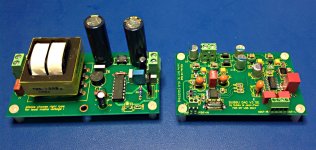
As life would have it I am just getting to this project. I finished my DAC tonight and had a chance to listen to it for about 3 hours so far. Wow it is fantastic! It is so detailed and dynamic just wonderful.
Thank you so much Jean-Paul and everyone that have shared their experiences with the build.
Thank you so much Jean-Paul and everyone that have shared their experiences with the build.
Attachments
I am making 4-way active speakers for my home hifi.
In each speaker i have one four chanel amplifier and two subbu V3 dac. I just plug two coax cable in to my speakers from my procesor and that`s it. I shorten speakers cable and rca cable as much as possible.
I wan`t to know what is better:
1. each subbu dac has his own psu
or
2. two subbu dac in one speaker has one psu
I have bought psu for each dac, but some one told me that it is better to have one psu for two dac. If i will use one psu for each dac that i am joust looking for trouble.
Please help me,
Thanks!
Hi,
have you a better choice than 2 PSU ? It could be a Pity to have more 10 cm wires between a Subbu and its PS board...
Are you talking about the genuine PS board or for an other PS unit ? I don't know if one genuine PSU has enough mA to feed two DAC boards. Some could help you here. Remenber some have measured it here or in the modyfing thread.
In an other way some active amp conf have multi DAC with multi PSU for it ! So Why not ?!
just try : proof of concept... not hard... just wires, your ears !
I finally finished my V3 DAC, I am using it with a JG buffer. I was wanting to add a wire headphone amp with a volume control to the normal outputs. Would it be best to switch the Volume pot and headphone out of the output when not listening to headphones?
Thanks
Bill
Thanks
Bill
Mini Inductors in 5V power supply
If anyone is in need of the small inductors (they were out at digikey last time I ordered) I purchase 25 off Ebay and have some extra .
Bill
If anyone is in need of the small inductors (they were out at digikey last time I ordered) I purchase 25 off Ebay and have some extra .
Bill
Hello all,
A friend of mine measured a subbu dac v3 and told me the SNR plot shows some spikes in 50 and 100Hz, around 84 db. From what I know he used an analyzer software and a cd with some sine to measure it in his laptop. He says that there seems to be some ground loop. In addition, the whole spectrum noise level seems to get lower some dbs, when removing the spdif cable from the cd.
Can anybody provide any suggestions? Do you think that there is some problem with the dac or with the way the measuremt was done? Finally, should I try to ground the dac?
Thanks in advance for any information.
P.S.
The dac is shown in http://www.diyaudio.com/forums/swap-meet/255778-fs-subbu-dac-v3-0-jg-buffer-finished.html .
Another friend of mine supports that the soldering of the dac is not
well done, and that this might be the problem. For example we found
a cold joint in one of the signals capacitors, and I was able to hear the difference
As I am measuring the dac I get 1.24V in C24 and C10, while the pic with voltages in this thread says 1.94 for both. Is this ok?
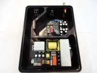
Please see picture 3 in the link you gave. 230 V AC mains wiring is close to the DAC board, in my book a big no no. I can't recall giving other info that to keep the DAC board as far away from 230 V AC wiring as possible. I also see a USB contraption of which I can not tell if it is wired correctly or not (GND).
Attachments
Last edited:
two cents : first remove the cabinet of the dac and listen to it on a wood plate, measure it if you want, with phisically at one side the 230 V and at the opposite side the 2 V. Try to do 10 cm gap for this test with wires between the PS output and the coreboard ps input. transformer must be away from the chips... for me too close on the photograph even if the transorler is at the opposite, he is also too near from the Buffer.
And the 230 V input above the coreboard is just a no-go.
If you have always a problem, check the solders. It can be normal they are not bright if the seller used 98 SN with 2% Au....
You can check all the voltages with the usefull photograph with the voltage values Phil (Korben69) posted in this thread but my understanding is you checked it already.
This DAC is sounding good. The tantalum 4.7 uf is not a problem at C17.
Last edited:
Thanks for all the info. The photos in that link, show the dac without the GaryB modifications. I have measured everything and the only difference that I find is that I get 1.24V in C10 and C24 instead of 1.94 V as provided in the voltage values Phil.
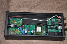
I removed the dac from the case and I think it sounds better now, though I have to measure it. There was a cable grounding DC- to the case. Could this be the problem?
In addition, the DC- of the PS is grounded to the chasis. Should the PS be grounded?
P.S.
I am building a Reflektor-D with a friend of mine for the DAC. When finished I will post impressions.
You found the reasons for the humm. IMO should audio-GND not be connected to the case or PE. Only the metal case should be connected to PE. This is debatable however. In some countries GND is always directly connected to PE. In my country this is not the case. Here PE should be connected to the metal case. I am quite certain this is legal with devices that take under 5 W of power like this DAC. I can only advise you to check regulations in your country.
You have 2 connections of audio-GND to the case which is at least one too many (IMO it are two too many 😉). If you want to connect audio-GND to the case (and thus PE) you should lift it to avoid a groundloop, again this is my personal opinion.
In the original setting this DAC was not well-wired regarding audio GND and 230 V AC crossing the audio section. It has never reached full potential. In a possible new setting it can. Have fun !
Last edited:
- Home
- Source & Line
- Digital Line Level
- Build thread - building the Subbu DAC V3 SE