Check the voltages after the regulators at L3 through L6, make sure that they match the guide at the beginning of the thread. Also study the schematic to see which reg feeds what and follow the path .
PINK
.
PINK
.
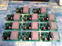
Here is a closer pic :

I don't know the brand it's from the group buy (from you Korben 🙂 ). I think it's written ASV F3F on it.
L3 voltage is fine : 3.23. C17 is 0 though.

I don't know the brand it's from the group buy (from you Korben 🙂 ). I think it's written ASV F3F on it.
L3 voltage is fine : 3.23. C17 is 0 though.
OK, C17 has 3,23V as well and then the XO probably is defective. You will need an oscilloscope to check that or just assume the XO is defective and replace it.
BTW you need to improve soldering skills somewhat. The ES9023 is not soldered properly. The joints look like soldered with lead free stuff. Use standard good quality 60/40 solder in 0,7 or even smaller diameter. Drag soldering is the way to go when you solder such a chip. Just flow all pins with lots of solder. Then use "solder wick"/ desoldering braid and remove excess solder in one draw. You can't correct it like that anymore but is might come handy to try that in the future.
BTW you need to improve soldering skills somewhat. The ES9023 is not soldered properly. The joints look like soldered with lead free stuff. Use standard good quality 60/40 solder in 0,7 or even smaller diameter. Drag soldering is the way to go when you solder such a chip. Just flow all pins with lots of solder. Then use "solder wick"/ desoldering braid and remove excess solder in one draw. You can't correct it like that anymore but is might come handy to try that in the future.
Last edited:
OK, C17 has 3,23V as well and then the XO probably is defective. You will need an oscilloscope to check that or just assume the XO is defective and replace it.
Thank you. Since I have no oscilloscope I'll assume it is defective.
Real question now is hpw to desolder it ? 😕
BTW you need to improve soldering skills somewhat. The ES9023 is not soldered properly. The joints look like soldered with lead free stuff. Use standard good quality 60/40 solder in 0,7 or even smaller diameter. Drag soldering is the way to go when you solder such a chip. Just flow all pins with lots of solder. Then use "solder wick"/ desoldering braid and remove excess solder in one draw. You can't correct it like that anymore but is might come handy to try that in the future.
I should be able to improve, since it's my first time doing SMD soldering I guess I can still improve 🙂 Though I do have 60/40 solder.
Anyway I'l follow your advice, but I think I could still use the desoldering braid.
That is hard. You will need a very thin knife (scalpel) and then heat one contact at the time and put a slight force upwards by tilting the scalpel. A hot air gun makes it almost a breeze but I guess you don't have one of those.
That is hard. You will need a very thin knife (scalpel) and then heat one contact at the time and put a slight force upwards by tilting the scalpel. A hot air gun makes it almost a breeze but I guess you don't have one of those.
I have a hot air gun but I'm afraid I'll heat all the parts around Q2, I can't focus the air flow only on Q2.
With an SMD hot air gun (not a paint stripper 😉) and some sheet metal and/or kapton tape to shield the parts you don't want to heat it should be possible.
It is possible if no SMD hot air gun to desolder Q2 but assume it's more risky ! I do it (with no wine before & succees just with an soldering iron and a little solder breads and of course a little screwdriver or scalpel... avoid knife à la Rambo !). Check before also the voltages of W8805 with Korben 's picture if not done already !
Last edited:
I have a hot air gun but I'm afraid I'll heat all the parts around Q2, I can't focus the air flow only on Q2.
Can you try reflowing c17 and check values again.
I have seen my friends removing Q2 couple of times with the help of two solders. Although they had to remove c17, R7 and L3 first. If someone can help you, removing smd parts aren't tough to remove with two solders.
Once you remove Q2, solder Q2 to PCB with the help of wires. I doubt your Q2 is fired. Nothing to loose. You can check the values n be assured whether Q2 is fired. Wires can desoldered easily from PCB.
It is possible if no SMD hot air gun to desolder Q2 but assume it's more risky ! I do it (with no wine before & succees just with an soldering iron and a little solder breads and of course a little screwdriver or scalpel... avoid knife à la Rambo !). Check before also the voltages of W8805 with Korben 's picture if not done already !
Thank for the advice. I'll consider buying a hot air gun... I have time since I need to order another Q2 first...
W8805 voltage seems OK, I've tested all pins, and they are OK.
Another cheaper option to remove SMD parts is ChipQuik. It's approximately $15 and it last quite a while. You don't need too much to remove a chip like the 9023.
A soldering air gun is very expensive. Canbe an investment,but reallydon'tneedsucha tool here : just be carefull and take your time. technic of darshanjoshi is excelent also !
Once you remove Q2, solder Q2 to PCB with the help of wires.
Just don't do that. Connections need to be short for full performance. If the pads are cleaned with desolder braid a new XO is soldered quite easy as the pads already have a small coating of solder on them.
Just don't do that. Connections need to be short for full performance. If the pads are cleaned with desolder braid a new XO is soldered quite easy as the pads already have a small coating of solder on them.
Permanantly Q2 has to be on pads only. I suggested to use wires only to check Q2 is working before placing order a new one.
Q2 is sometimes difficult to solder and one would not be able to tell whether Q2 is fried or not working in case of insufficient contact between Q2 & any one of four pads.
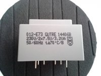
Please measure the rectified voltage as I hava a hunch those transformers give way more voltage than the Tamura ones.
We talk about jour suggestion on not using 2*9V transformer because of to big secondary winding voltages...
Because of high number of pcbs to solder, I didn* wont to risk so i deceided to buy this ones.
GUTRE 230V/2x7,5V/3,2A
Spec are here http://www.neuhold-elektronik.at/datenblatt/N7045.pdf
Ac volatge on recetifer at no load is about 9,3V and dc on first 2200Uf/16 Panasonic FM capacitor is 11,8V at no load, so this is perfect.
Just pins must be rearanged for mm or two because of fuse and bridge which are very close to the transformer.
Thanks
Attachments
- Home
- Source & Line
- Digital Line Level
- Build thread - building the Subbu DAC V3 SE